Sensor device

a sensor device and sensor technology, applied in the field of sensor devices, can solve the problems of offset voltage and low-frequency l/f noise in the output of the amplifier, and achieve the effects of accurate measurement of the temperature of an object, increased circuit size of the sensor device, and increased circuit size of the low-pass filter

Active Publication Date: 2012-06-14
PANASONIC INTELLECTUAL PROPERTY MANAGEMENT CO LTD
View PDF2 Cites 7 Cited by
  • Summary
  • Abstract
  • Description
  • Claims
  • Application Information

AI Technical Summary

Benefits of technology

The invention relates to improving accuracy when measuring temperatures by adding components such as resistors and capacitors that affect the performance of filters. This results in larger circuits which require bigger sensory devices. To address this problem, a digital converter can be added but it also requires multiple components and leads to even greater circuit sizes.

Problems solved by technology

The technical problem addressed in this patent relates to improving accuracy when measuring temperatures through a sensor device that uses a thermocoule or other sensing mechanism. Due to the small size of the resulting voltage signals, conventional amplifiers used in these devices can experience off-voltage and low-frequency noise which affect measurement accuracy. Chopping technology helps remove these issues by effectively isolating the offset voltage and low-frequency components while maintaining the desired temperature indication.

Method used


Image

  • Sensor device
  • Sensor device
  • Sensor device

Examples


Embodiment Construction

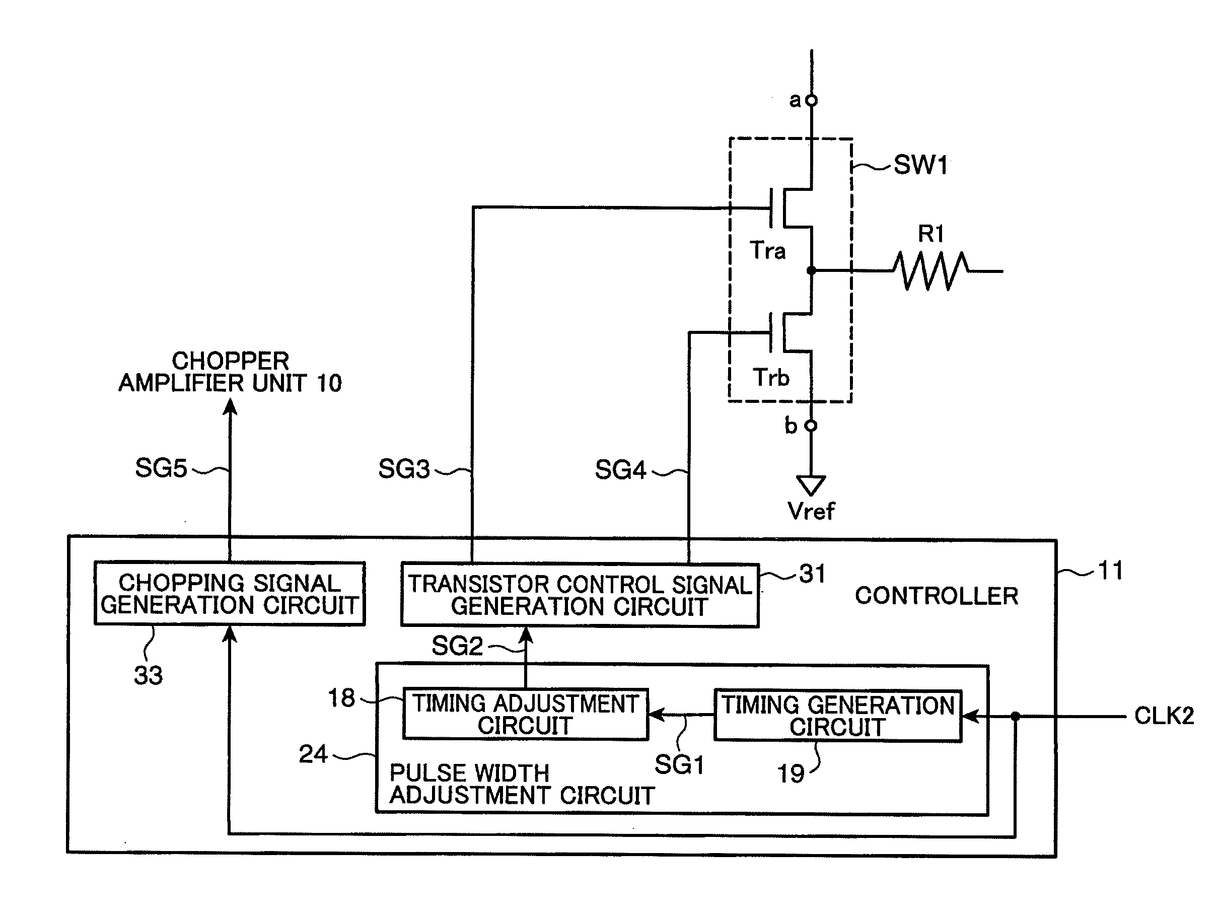
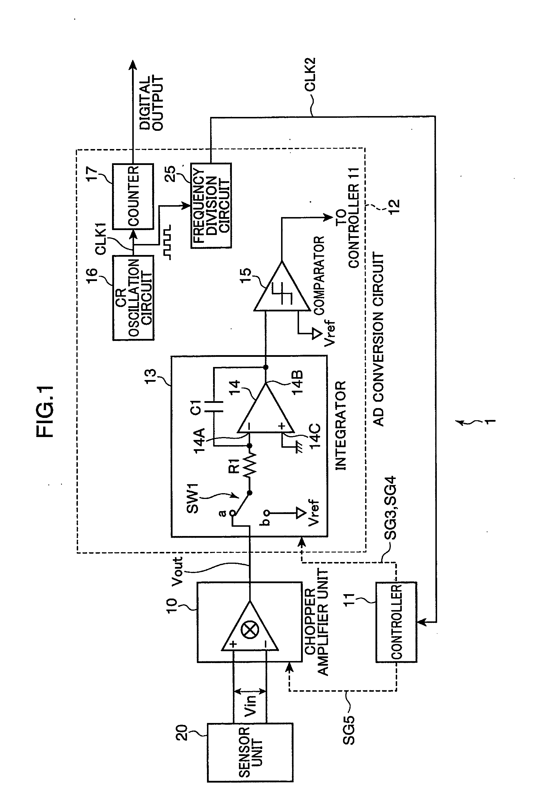
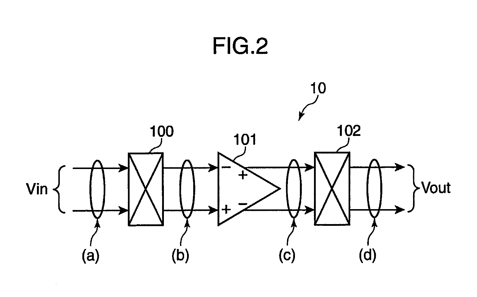
[0026]A sensor device according to one embodiment of the present invention is described below. FIG. 1 is a diagram showing an exemplary construction of the sensor device. FIG. 2 is a diagram showing an exemplary construction of a chopper amplifier unit. FIG. 3 shows graphs showing an exemplary operation of the chopper amplifier unit. FIG. 4 is a diagram showing an exemplary construction of an integrator.

[0027]The sensor device 1 shown in FIG. 1 includes a controller (control unit) 11. The controller 11 centrally controls respective constituent elements described below. The sensor device 1 further includes a voltage detection type sensor unit 20, a chopper amplifier unit 10 and an AD conversion circuit (digital conversion unit) 12. The sensor unit 20 converts a physical quantity into a voltage value and outputs a voltage signal indicating this voltage value.

[0028]The chopper amplifier unit 10 includes a first chopper circuit 100, an operational amplifier 101 and a second chopper circ...


PUM


Abstract

A sensor device is provided with a voltage detection type sensor unit for converting a physical quantity into a voltage value and outputting a voltage signal indicating the voltage value; a chopper amplifier unit for generating a modulation signal by chopping the voltage signal output from the sensor unit with a predetermined chopping frequency, amplifying the modulation signal into an amplification signal, then demodulating the amplification signal and outputting it as an output signal; an integration unit including an operational amplifier, an input resistor connected to the inverting input terminal of the operational amplifier and a capacitor connected between the inverting input terminal and an output terminal of the operational amplifier; and a digital conversion unit for converting the output signal integrated by the integration unit into a digital signal.

Description


Claims


Application Information

Patent Timeline
Owner PANASONIC INTELLECTUAL PROPERTY MANAGEMENT CO LTD
Why Eureka
Try Eureka