Ceramic honeycomb structure and its production method

a honeycomb and honeycomb technology, applied in the field of honeycomb structure, can solve the problems of increased pressure loss, insufficient, adversely affecting humans and environment when discharged into the air, etc., and achieve the effect of suppressing pressure loss increase and improving pm-capturing ratio

Active Publication Date: 2012-06-14
HITACHI METALS LTD
View PDF8 Cites 20 Cited by
  • Summary
  • Abstract
  • Description
  • Claims
  • Application Information

AI Technical Summary

Benefits of technology

[0016]An object of the present invention is to provide a ceramic honeycomb structure having an improved PM-capturing ratio at an early stage of use after the regeneration of a ceramic honeycomb filter, with suppressed pressure loss increase when PM is captured, and its production method.

Problems solved by technology

An exhaust gas discharged from diesel engines contains particulate matter (PM) comprising as main components carbonaceous soot and soluble organic fractions (SOFs) comprising high-boiling-point hydrocarbon components, which are likely to adversely affect humans and environment when discharged into the air.
PM continuously captured by the cell walls 2 clogs communicating pores on and in the cell walls 2, resulting in increased pressure loss when the exhaust gas passes through the ceramic honeycomb filter.
However, the exhaust-gas-cleaning filters described in JP 2005-530616 A, JP 2002-219319 A, JP 61-129015 A, JP 2003-40687 A, JP 2002-355511 A, and JP 2002-349234 A exhibit PM-capturing performance, which becomes high by the accumulation of PM to some extent, but is not necessarily sufficient at an early stage of use before PM is accumulated (when the ceramic honeycomb filter starts to be freshly used or reused after regeneration).
Particularly they fail to capture harmful, nano-sized PM sufficiently, but discharge it, causing a serious problem under the strengthened exhaust gas regulations.
However, even the ceramic honeycomb filter described in JP 2004-360654 A fails to solve the problem of low PM-capturing efficiency at an early stage of use after its regeneration.
However, when the porous resin particles are used as a pore-forming material, high pressure is needed in the extrusion molding because of friction resistance among the pore-forming material particles, likely resulting in the deformation of extrudates and dies.

Method used


Image

  • Ceramic honeycomb structure and its production method
  • Ceramic honeycomb structure and its production method
  • Ceramic honeycomb structure and its production method

Examples


Embodiment Construction

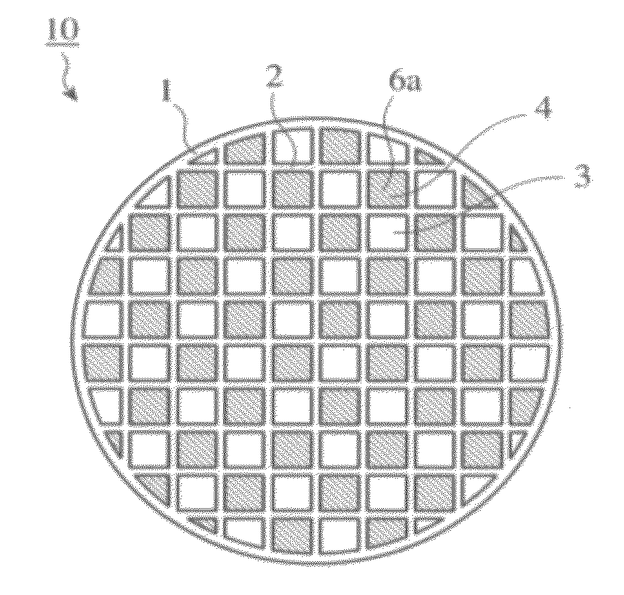
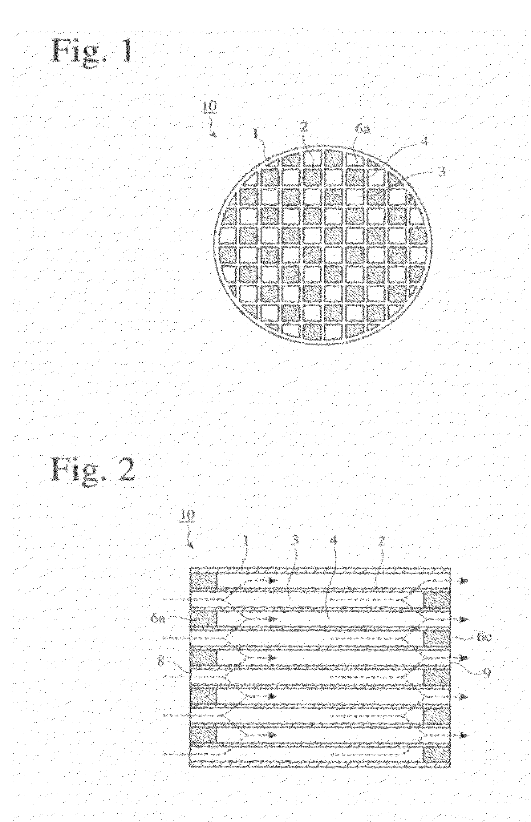
[0045][1] Ceramic Honeycomb Structure

[0046](1) Structure

[0047]The ceramic honeycomb structure of the present invention has a large number of flow paths partitioned by porous cell walls,

[0048]the cell walls having porosity of 40-60%;

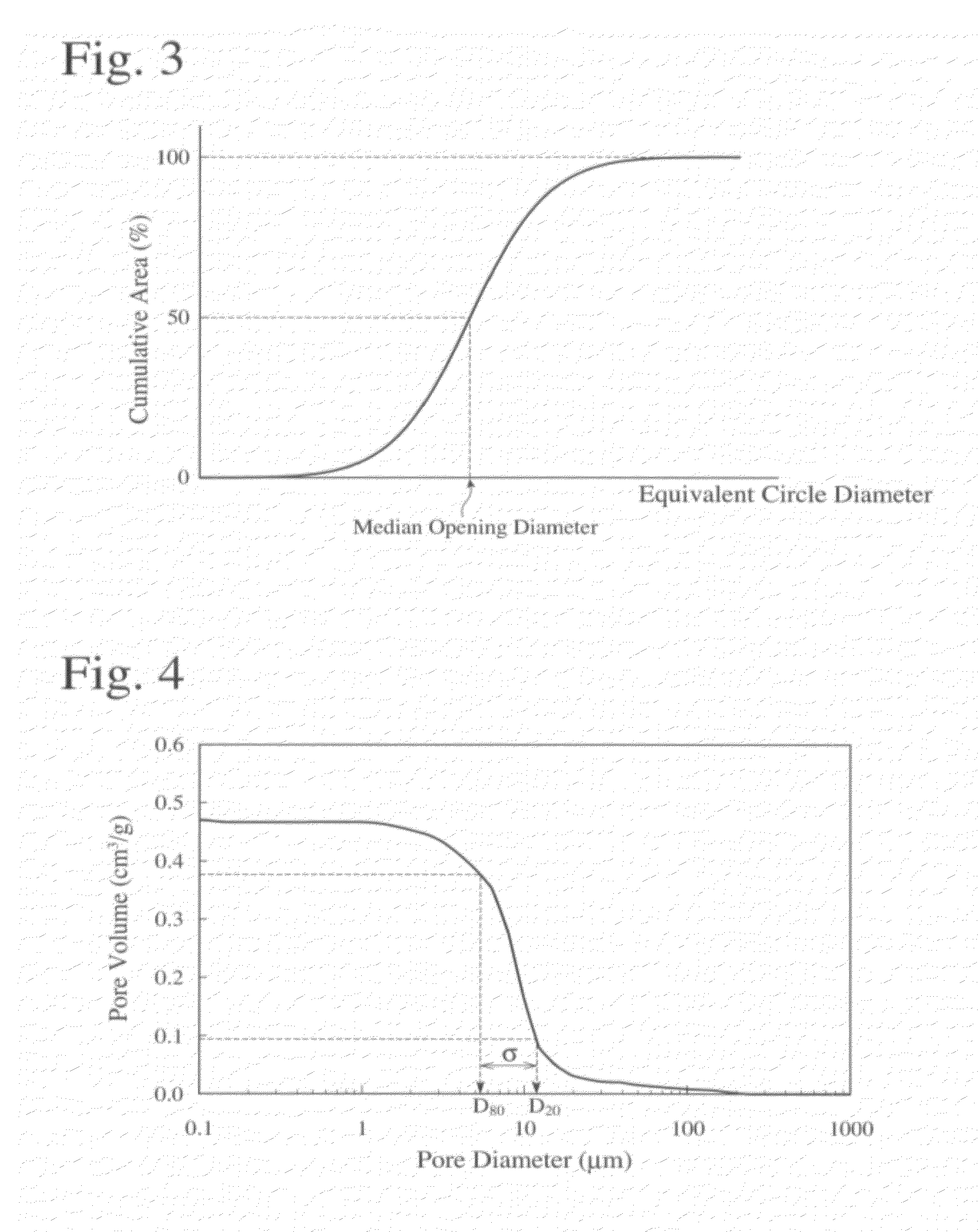
[0049]pores opening on the cell wall surface having an opening area ratio (the total opening area of pores opening on the cell wall surface per a unit area) of 15% or more;

[0050]when the opening diameter of each pore opening on the cell wall surface is expressed by an equivalent circle diameter (a diameter of a circle having the same area as the opening area of each pore), the median opening diameter of the opening pores being 10 μm or more and less than 40 μm;

[0051]the density of pores having equivalent circle diameters of 10 μm or more and less than 40 μm being 350 / mm2 or more; and

[0052]the average circularity of pores having equivalent circle diameters of 10 μm or more and less than 40 μm being 1-2.

[0053]With such structure, the ceramic honeycomb struc...


PUM

PropertyMeasurementUnit
porosityaaaaaaaaaa
median opening diameteraaaaaaaaaa

Abstract

A ceramic honeycomb structure having a large number of flow paths partitioned by porous cell walls, the cell walls having porosity of 40-60%; pores opening on the cell wall surface having an opening area ratio (the total opening area of pores opening on the cell wall surface per a unit area) of 15% or more; the median opening diameter of the opening pores being 10 μm or more and less than 40 μm, when the opening diameter of each pore opening on the cell wall surface is expressed by an equivalent circle diameter (a diameter of a circle having the same area as the opening area of each pore); the density of pores having equivalent circle diameters of 10 μm or more and less than 40 μm being 350/mm2 or more; and the average circularity of pores having equivalent circle diameters of 10 μm or more and less than 40 μm being 1-2.

Description

FIELD OF THE INVENTION[0001]The present invention relates to a ceramic honeycomb structure for constituting a ceramic honeycomb filter for removing fine particles from exhaust gases discharged from diesel engines.BACKGROUND OF THE INVENTION[0002]An exhaust gas discharged from diesel engines contains particulate matter (PM) comprising as main components carbonaceous soot and soluble organic fractions (SOFs) comprising high-boiling-point hydrocarbon components, which are likely to adversely affect humans and environment when discharged into the air. Accordingly, ceramic honeycomb filters have conventionally been attached to exhaust pipes of diesel engines for removing PM.[0003]One example of ceramic honeycomb filters for capturing PM in the exhaust gas is shown in FIGS. 1 and 2. The ceramic honeycomb filter 10 comprises a ceramic honeycomb structure comprising porous cell walls 2 defining a large number of outlet-side-sealed flow paths 3 and inlet-side-sealed flow paths 4 and a periph...

Claims


Application Information

Patent Timeline
Patent Type & Authority Applications(United States)
IPC IPC(8): B32B3/12B29C39/00
CPCC04B35/195Y10T428/24149C04B38/067C04B38/068F01N3/0222F01N2330/06Y02T10/20B01D39/2068B01D2239/1208B01D2239/1216B01D2239/125B01D2239/1258B01D2046/2433B01D2046/2437B01D46/2429C04B38/0009C04B2111/00793C04B2111/0081C04B2235/3217C04B2235/3418C04B2235/3445Y02T10/12B01D46/24492B01D46/24491B01D46/24494C04B38/0054B01D46/0001B01D46/2455B01D46/2474B01D46/2482B01D46/2484B01D46/2425C04B38/0006
Inventor OKAZAKI, SHUNJI
Owner HITACHI METALS LTD
Why Eureka
Try Eureka