Method for Machining a Dental Prosthesis

a technology for dental prostheses and machining methods, which is applied in the field of manufacturing dental prostheses, can solve the problems of small forming tools that are not as strong as larger forming tools of the same quality, dental prostheses that are difficult to machine than materials of lesser hardness, and the likelihood of forming tools being prone to failure, so as to reduce the likelihood of forming tools failing and improve the likelihood of forming tools

Inactive Publication Date: 2012-06-14
JUNG YUNOH +1
View PDF0 Cites 51 Cited by
  • Summary
  • Abstract
  • Description
  • Claims
  • Application Information

AI Technical Summary

Benefits of technology

[0006]It has been recognized that it would be advantageous to develop a method for machining a dental prosthesis that reduces the likelihood of forming tool failure.
[0007]The invention provides a method of manufacturing a dental prosthesis, including obtaining a workpiece having a proximal end attached to a fixture configured to engage with a machine tool and engaging the fixture with the machine tool. The method further provides for machining the workpiece with a forming tool to form a top surface and at least a portion of a side surface of the dental prosthesis. This may be followed by rotating the machine tool and the workpiece relative to each other about a rotational axis of the fixture. The method then provides for machining the workpiece with the forming tool to form at least a portion of a connector between a proximal end of the dental prosthesis and the proximal end of the workpiece, the connector having a strength sufficient to withstand a subsequent machining operation to form the dental prosthesis. Additionally, the method provides for machining the workpiece with the forming tool to form a bottom surface of the dental prosthesis, the forming tool following a spiral tool path moving inward from an outer perimeter of the dental prosthesis. Such a method has been found to greatly improve the likelihood that a forming tool will not fail during machining a dental prosthesis.

Problems solved by technology

The drawback is that a small tool is not as strong as a larger tool of the same quality.
Harder materials are more difficult to machine than materials of lesser hardness.
The smaller forming tools typically used to machine dental prostheses may be prone to failure due to the increased stress of machining harder materials and this may be particularly troublesome when machining a bottom surface of a dental prosthesis.

Method used


Image

  • Method for Machining a Dental Prosthesis
  • Method for Machining a Dental Prosthesis
  • Method for Machining a Dental Prosthesis

Examples


Embodiment Construction

)

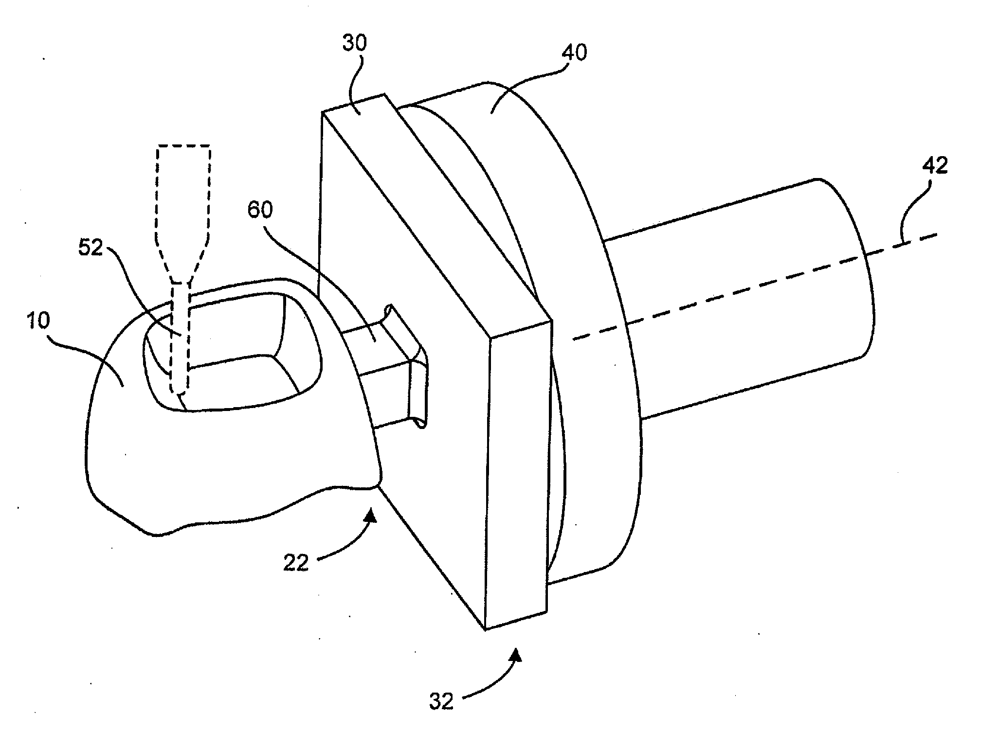
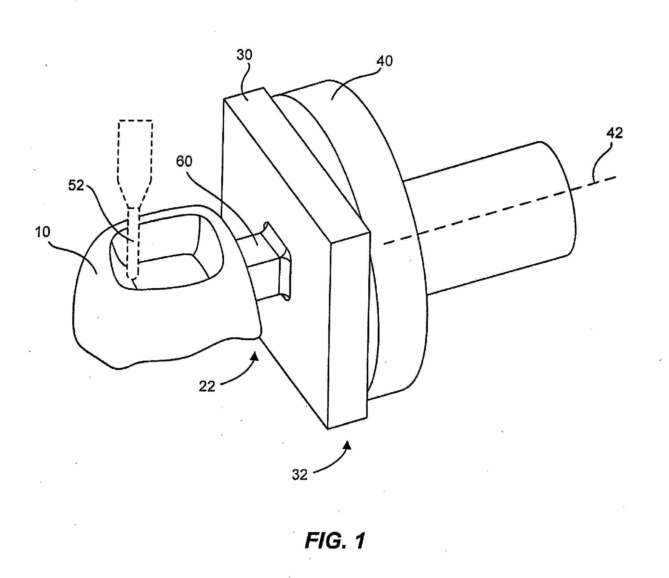
[0022]Illustrated in FIG. 1 is a dental prosthesis 10 during manufacture in an example embodiment in accordance with the invention. In this embodiment, a workpiece 30 may be attached to a fixture 40. A connector 60 may be between a proximal end 22 of the dental prosthesis 10 and a proximal end 32 of the workpiece 30. Also illustrated is that the dental prosthesis 10 may be formed by a forming tool 52. A workpiece 30 may comprise any suitable dental prosthesis material, for example, machinable ceramics such as sintered ceramics (i.e. feldspar ceramic) and partially sintered ceramics (i.e. zirconium oxid and aluminium oxid), titanium, gold, glass, acrylic, etc.

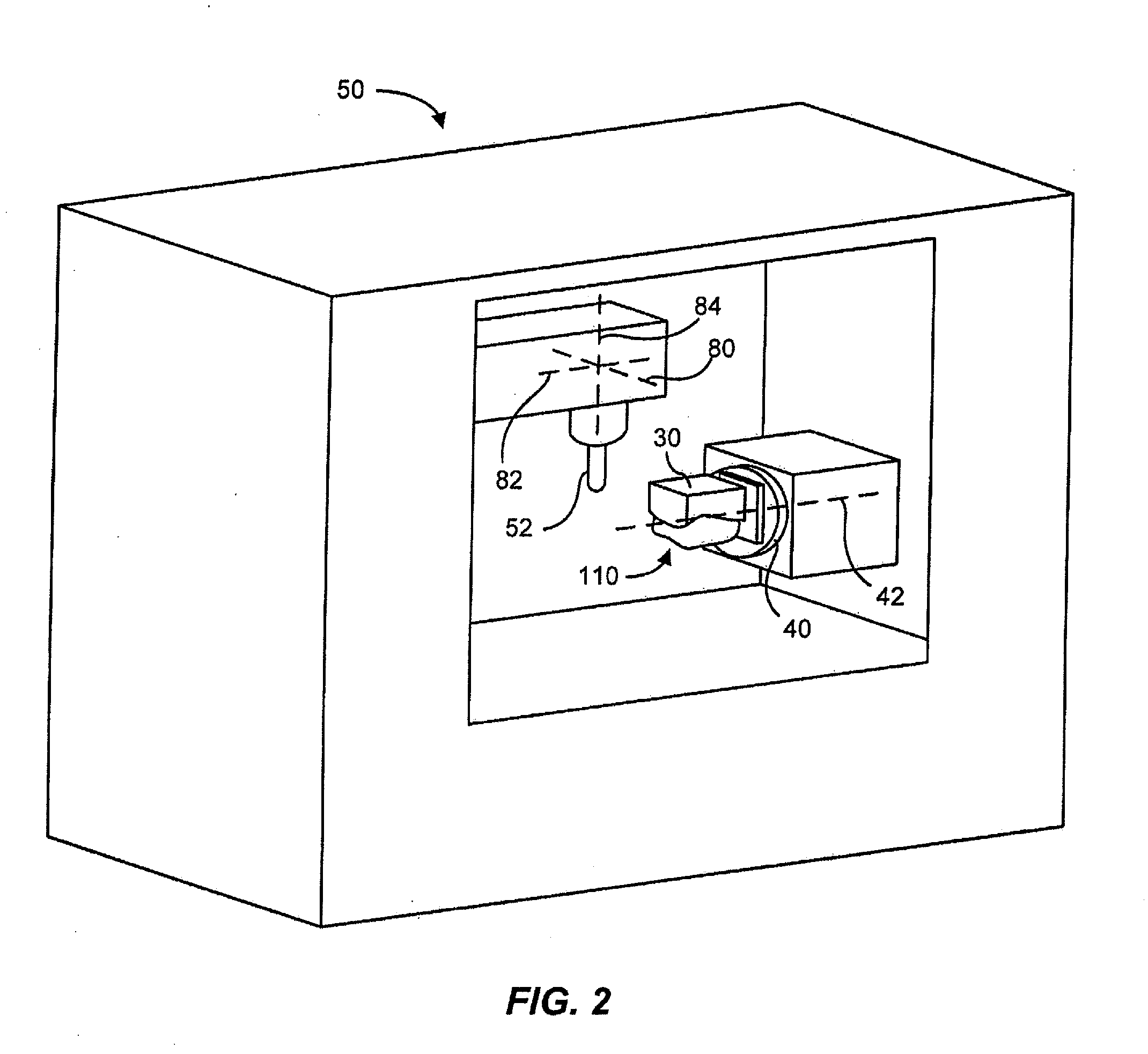
[0023]As illustrated in FIG. 2, a dental prosthesis 10 may be formed using a machine tool 50. A machine tool 50 may provide linear movement in at least three axes 80, 82, 84 and rotational movement about at least one axis 42. For example, a machine tool 50 may provide linear movement in X, Y, and Z orthogonal axes. In one aspec...


PUM


Abstract

A method for machining a dental prosthesis that reduces the likelihood of forming tool failure includes machining a workpiece to form a top surface and a side surface of the dental prosthesis, machining a connector between a proximal end of the dental prosthesis and a proximal end of the workpiece, and machining a bottom surface of the dental prosthesis with a spiral tool path.

Description

BACKGROUND[0001]1. Field of the Invention[0002]The present invention relates generally to manufacturing a dental prosthesis. More particularly, the present invention relates to machining a dental prosthesis.[0003]2. Related Art[0004]Various different methods have been developed for manufacturing dental prostheses. One type of manufacturing process used to manufacture dental prostheses is machining. A machining process may form a part by removing material. A forming tool may be used to remove material. Typical forming tools may remove material by cutting or abrading. For example, an end mill is a typical “cutter” and a grinder is typical of an abrading tool. A machine tool rotates the forming tool, typically at a high speed, so that the forming tool can remove material from a workpiece. A typical workpiece may begin as a solid block of material. Successive passes with the forming tool may be necessary to remove enough material from the workpiece to achieve a final part.[0005]In machi...

Claims


Application Information

Patent Timeline
Patent Type & Authority Applications(United States)
IPC IPC(8): A61C5/10A61C5/77
CPCA61C13/08A61C13/0022
Inventor JUNG, YUNOHJUNG, DANIEL YONIL
Owner JUNG YUNOH
Why Eureka
Try Eureka