Method of manufacturing blazed diffractive grating and method of manufacturing mold for manufacturing blazed diffractive grating

a manufacturing method and diffractive grating technology, applied in the field of a manufacturing method of a mold for manufacturing a blazed diffractive grating, can solve the problems of reducing manufacturing efficiency and the time required to process grooves too long, and achieve the effect of improving manufacturing efficiency

Active Publication Date: 2012-06-21
CANON KK
View PDF9 Cites 9 Cited by
  • Summary
  • Abstract
  • Description
  • Claims
  • Application Information

AI Technical Summary

Benefits of technology

[0007]The present invention provides, for example, a method of manufacturing a blazed diffractive grating, which is advantageous in terms of manufacturing efficiency.

Problems solved by technology

In the conventional technique of repeatedly performing a shallow cutting process many times to form one groove, the time required to process grooves is too long, thereby reducing the manufacturing efficiency.

Method used


Image

  • Method of manufacturing blazed diffractive grating and method of manufacturing mold for manufacturing blazed diffractive grating
  • Method of manufacturing blazed diffractive grating and method of manufacturing mold for manufacturing blazed diffractive grating
  • Method of manufacturing blazed diffractive grating and method of manufacturing mold for manufacturing blazed diffractive grating

Examples


Embodiment Construction

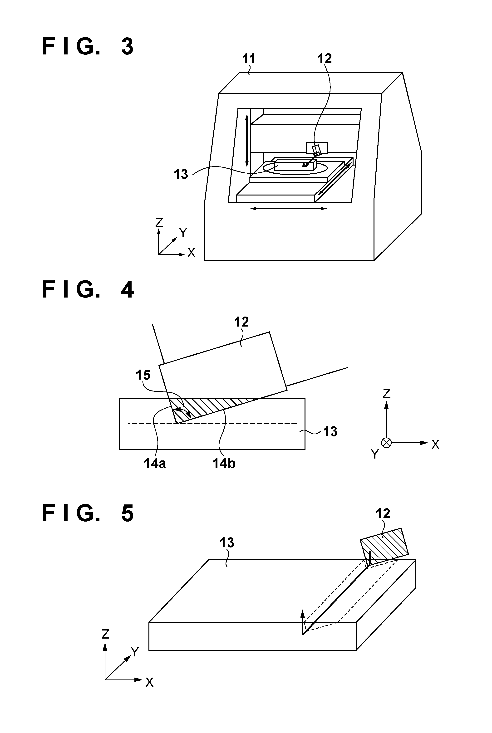
[0020]To explain the present invention, an embodiment for manufacturing a brazed diffractive grating by groove processing will be shown. A cutting machine used to manufacture a blazed diffractive grating is a position-controllable high-precision machine which can instruct cutting on the order of several tens of nanometers. As a tool, a cutting tool such as a diamond cutting tool whose tip is sharp and whose machining transfer property is high is used. The material of an object is selected from copper-, aluminum-, and electroless nickel-based materials which have high machinability by a diamond cutting tool.

[0021]FIG. 3 shows an overview of the arrangement of a cutting machine 11, a cutting tool 12, and an object 13 used in this embodiment. The cutting machine 11 has a gate-shaped, high-rigidity structure, resists external vibrations and the like, and is appropriate for superhigh-resolution, position-controllable, ultraprecision cutting. In the cutting machine 11, the cutting tool 12...


PUM

PropertyMeasurementUnit
opening angleaaaaaaaaaa
cutting depthaaaaaaaaaa

Abstract

A method of manufacturing a blazed diffractive grating includes a first step of forming a first groove having a first surface and a second surface by moving, in the first direction at a first position in the second direction, a cutting tool having a first cutting blade and a second cutting blade to cut the object; a second step of forming a second groove by moving, in the first direction at a second position separated from the first position in the second direction by a grating pitch, the cutting tool to cut the object; and a third step of forming a blazed surface of the first groove using the first cutting blade by moving, in the first direction at a third position between the first position and the second position, the cutting tool to cut the first surface of the first groove.

Description

BACKGROUND OF THE INVENTION[0001]1. Field of the Invention[0002]The present invention relates to a method of manufacturing a blazed diffractive grating and a method of manufacturing a mold for manufacturing a blazed diffractive grating.[0003]2. Description of the Related Art[0004]As shown in FIG. 1, a blazed diffractive grating has asymmetrical triangular grooves, and includes a blazed surface 2′ on which light 7 is incident, and a counter surface 3 adjacent to the blazed surface 2′. The blazed surface 2′ and counter surface 3 respectively tilt at predetermined angles with respect to a grating surface 4. In such a blazed diffractive grating, the diffraction efficiency must be concentrated on a given order. To achieve a high diffraction efficiency, it is required that the blazed surface 2′ is flat and its unevenness or roughness is small. A cutting volume largely influences the flatness of the blazed surface 2′. If a cutting volume in one cutting process is large, burrs and surface r...

Claims


Application Information

Patent Timeline
Patent Type & Authority Applications(United States)
IPC IPC(8): B26D3/06
CPCG02B5/1852B29D11/00769G02B5/1861G02B5/1857Y10T83/0304
Inventor SUKEGAWA, TAKASHIOKURA, YUKINOBU
Owner CANON KK
Why Eureka
Try Eureka