
Solenoid for a Direct Acting Valve Having Stepped Guide Tube

Inactive Publication Date: 2012-06-21
ROBERTSHAW CONTROLS CO
View PDF10 Cites 19 Cited by
  • Summary
  • Abstract
  • Description
  • Claims
  • Application Information

AI Technical Summary

Benefits of technology

[0008]In view of the above, embodiments of the present invention provide a new and improved solenoid for a solenoid type direct acting valve. More particularly, embodiments of the present invention provide a new and improved solenoid for a solenoid type direct acting valve having reduced material costs realized through a reduction in the amount of copper used in the solenoid coil therein. Other embodiments of the invention provide a new and improved solenoid type direct acting valve that utilizes a solenoid in accordance with the teachings of the present invention.
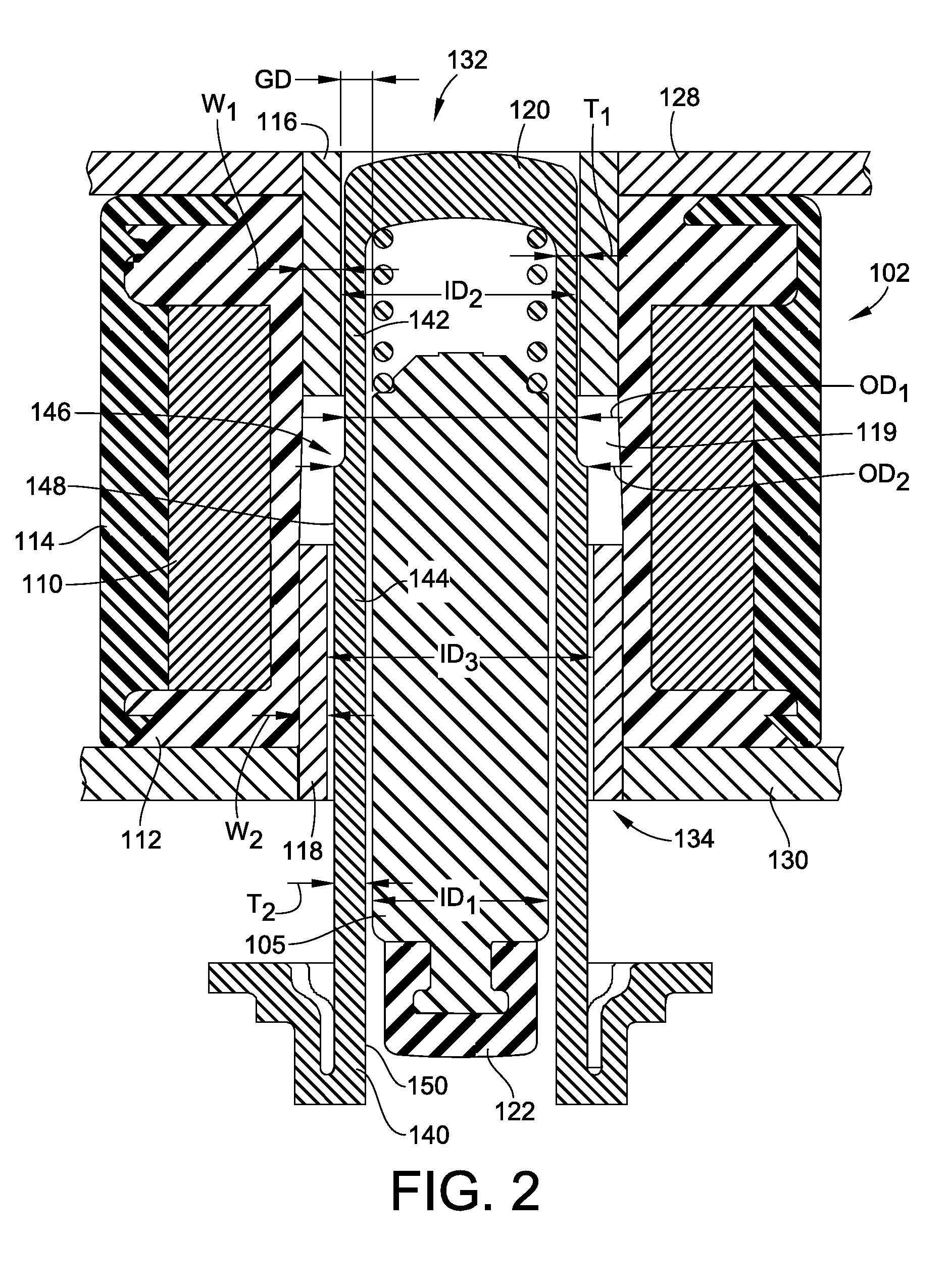
[0011]In one embodiment, the solenoid further includes a generally cylindrical upper pole piece and a generally cylindrical lower pole piece. The lower portion of the guide tube passing through the lower pole piece and the upper portion of the guide tube passing through the upper pole piece. The pole pieces reduce reluctance and increase the efficiency of the magnetic circuit.

Problems solved by technology

One cause of resistance to magnetic flux can be caused by a gap in the circuit.
Unfortunately, the cost of copper has increased more than three hundred percent in recent years.
This significant price increase has significantly increased the cost of the solenoid actuator coil to a point where the solenoid coil now provides a significant cost of the valve as a whole (about fifty percent).
Unfortunately, in such a competitive industry, the difference of only a few cents can make or break a major sale.
Countering this copper reduction effort, however, is the requirement for reliable operation at each actuation and continued long life of such valves.

Method used


Image

  • Solenoid for a Direct Acting Valve Having Stepped Guide Tube
  • Solenoid for a Direct Acting Valve Having Stepped Guide Tube
  • Solenoid for a Direct Acting Valve Having Stepped Guide Tube

Examples


Embodiment Construction

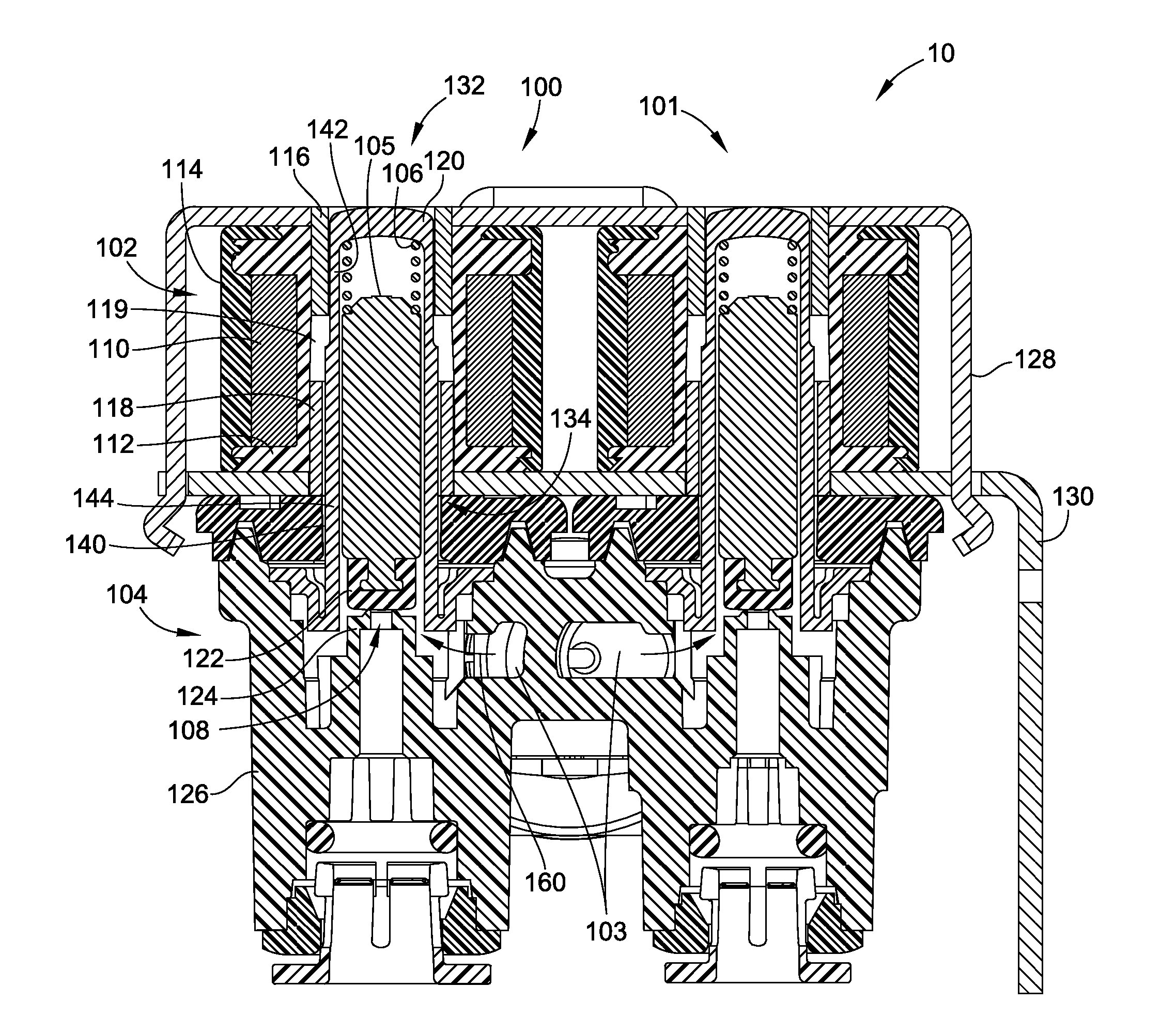
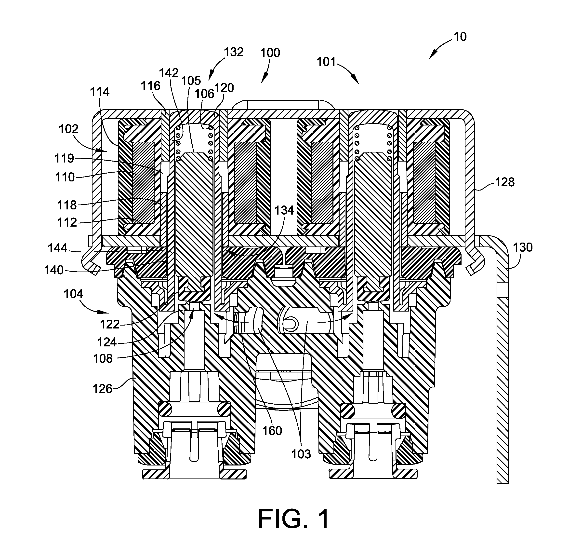
[0024]Turning now to the drawings, and particularly to FIG. 1, there is illustrated in partial cross-sectional form an embodiment of a water valve 10 for controlling water supply to two separate functions within an appliance. In this embodiment, the water valve 10 includes a pair of solenoid type direct acting valves 100, 101. The solenoid type direct acting valves 100, 101 control water flow from a common water supply 103. This embodiment is configured such that solenoid type direct acting valve 100 controls water flow to an ice maker within a refrigerator and solenoid type direct acting valve 100 controls water flow to a water dispenser of the refrigerator.

[0025]The two solenoid type direct acting valves 100, 101 are substantially similar in construction and operation. As such only solenoid type direct acting valve 100 will be described and will be also referred to herein as “solenoid valve 100” for simplicity. The following description for solenoid valve 100 will be equally appli...


PUM


Abstract

A solenoid for a direct acting solenoid valve having reduced copper in a coil thereof is provided. The solenoid utilizes a stepped profile for a guide tube thereof, which reduces reluctance in the magnetic circuit such that a coil with less copper windings can be used. A direct acting solenoid valve utilizing such a reduced copper solenoid is also provided.

Description

FIELD OF THE INVENTION[0001]This invention generally relates to electrically actuated valves of the type employed for control of water inlet flow to appliances such as for water dispensers and ice makers for refrigerators as well as for dishwashers and washing machines.BACKGROUND OF THE INVENTION[0002]Water valves for appliances often employ solenoid type direct acting valves. The solenoid assembly creates the linear force to displace an armature for opening and closing the orifice of the valve.[0003]In the off position, the armature is forced in a closed position by means of a heavy spring force. To open the valve, the magnetic force of the solenoid must overcome the heavy force of the spring and the pressure force. In such a case, the solenoid relies on a properly sized copper coil.[0004]Reluctance is the resistance of magnetic flux in a magnetic circuit. One cause of resistance to magnetic flux can be caused by a gap in the circuit. One particular gap can be directly related to t...

Claims


Application Information

Patent Timeline
IPC IPC(8): F16K31/02
CPCF16K27/029F16K31/0624H01F7/1607F16K31/0679H01F7/081F16K31/0658
Inventor NGUYEN, TAM
Owner ROBERTSHAW CONTROLS CO
Learn More