Compound Rim Assembly For Idler In An Undercarriage System Of A Track-Type Machine

a track-type machine and idler technology, applied in mechanical equipment, transportation and packaging, hoisting equipment, etc., can solve the problems of metal-on-metal wear of many undercarriage system components, subject undercarriage systems to substantial wear, and achieve lower hardness, higher hardness, and lower hardness of metallic materials

Active Publication Date: 2012-06-21
CATERPILLAR INC
View PDF4 Cites 28 Cited by
  • Summary
  • Abstract
  • Description
  • Claims
  • Application Information

AI Technical Summary

Problems solved by technology

Many undercarriage system components experience metal-on-metal wear during service.
In addition, abrasive materials are present at most worksites where track-type machines are used.
The metal-on-metal contact between and among undercarriage system components, exacerbated by abrasive materials, can subject undercarriage systems to substantial wear.
Rotation of the one or more drive sprockets and idler against components of the track such as the track links and / or track shoes, and particularly where abrasive materials intrude between the drive sprocket or idler and the track, can wear away material such that dimensions, contact patterns, and other geometric properties of the subject components tend to change over time.
Although the use of idler recoil systems and the like can extend track service life over what might otherwise be possible, eventually wear on the idler and / or other undercarriage system components necessitates track servicing or rebuild if efficient use of the machine, and in some cases any use, is to continue.
Repair technicians may perform a very labor intensive process known in the art as “hard facing” in which numerous layers of material are deposited one upon the other on the outer surface of the idler.
While in many instances a hard facing process can be economically superior over purchasing a new idler, idlers repaired in this manner may have reduced robustness and greater susceptibility to certain types of wear than a new idler, and suffer from other shortcomings.

Method used


Image

  • Compound Rim Assembly For Idler In An Undercarriage System Of A Track-Type Machine
  • Compound Rim Assembly For Idler In An Undercarriage System Of A Track-Type Machine
  • Compound Rim Assembly For Idler In An Undercarriage System Of A Track-Type Machine

Examples


Embodiment Construction

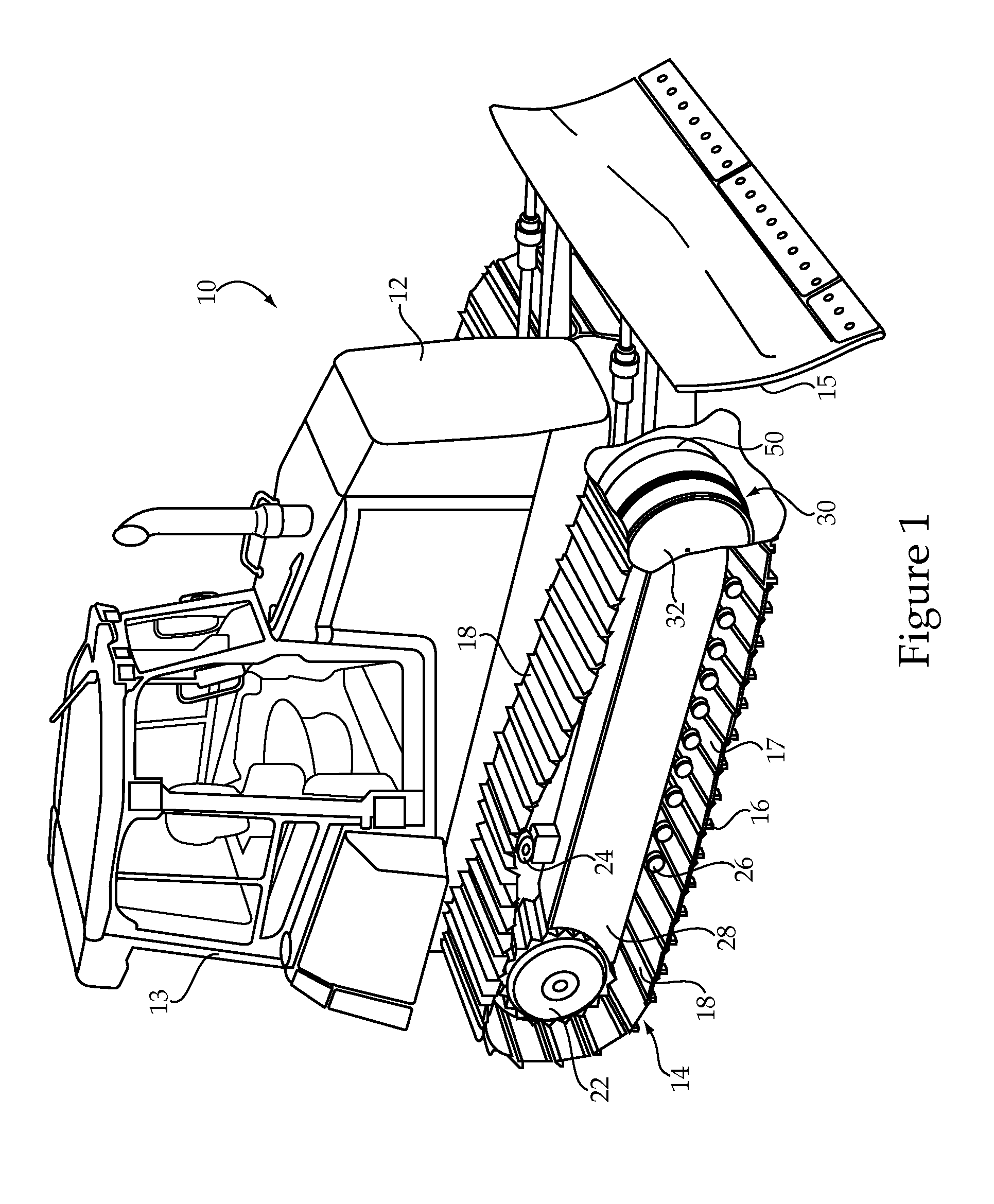
[0013]Referring to FIG. 1, there is shown a machine 10 according to one embodiment. Machine 10 includes a frame 12, and an undercarriage system 14 coupled with frame 12. An operator cab 13 is positioned upon frame 12, and an implement 15 is also coupled with frame 12. Machine 10 is shown in the context of a track-type tractor, however, it should be appreciated that machine 10 might include an excavator, a track loader, or still another type of machine. Implement 15 is shown as a blade, however, it will similarly be appreciated that a variety of different implements such as a bucket or the like might alternatively be used.

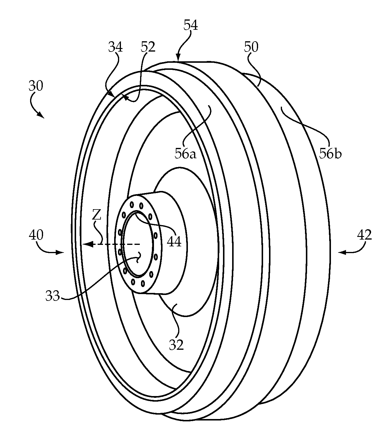
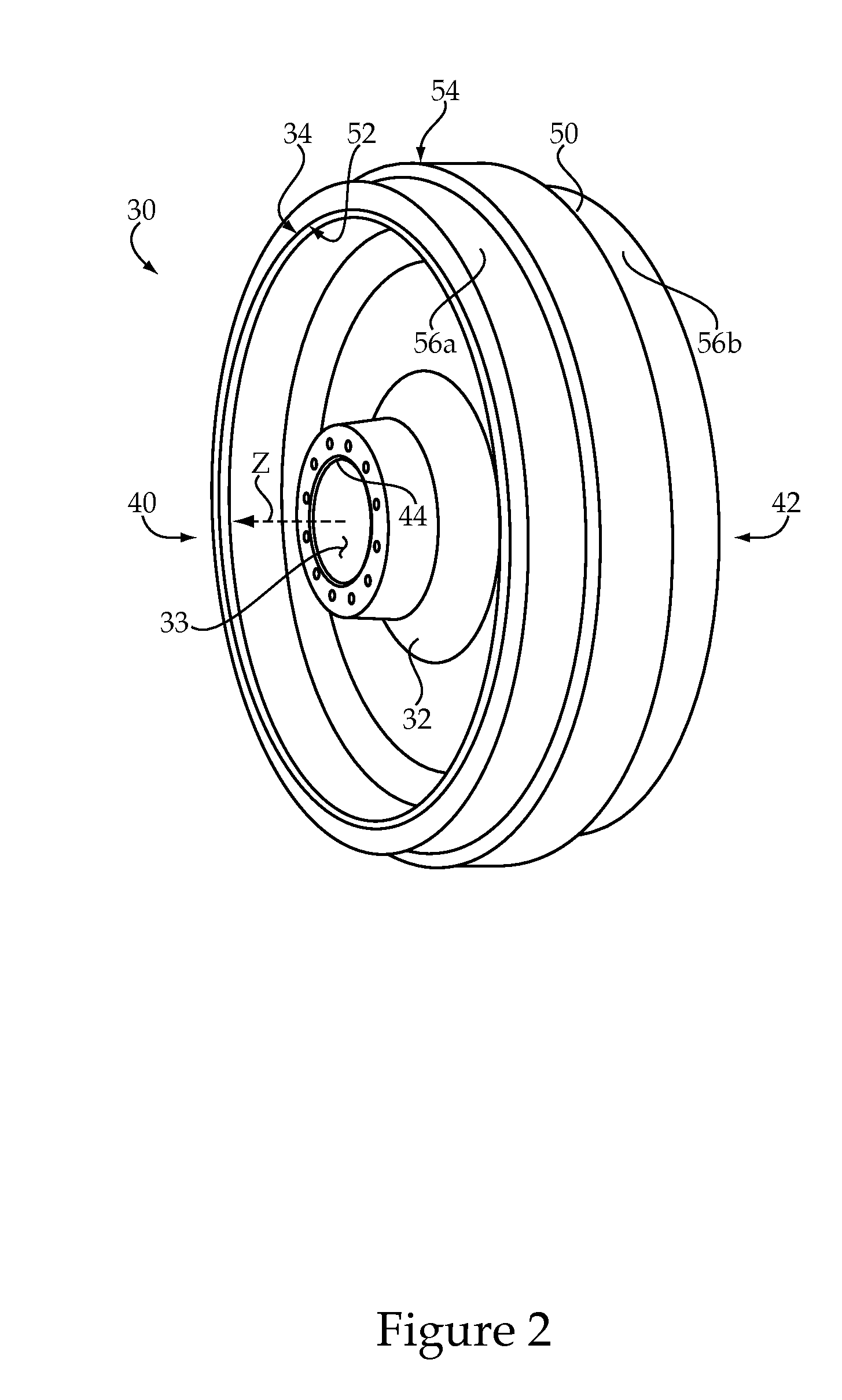
[0014]Undercarriage system 14 includes a drive sprocket 22, a rotatable idler 30, a track roller frame 28, and a ground engaging track 16. Track 16 may include one of two tracks positioned at opposite sides of machine 10 in a conventional manner. Accordingly, the present description of track 16 and associated components of undercarriage system 14 should be understoo...


PUM


Abstract

A compound rim assembly for a rotatable idler in an undercarriage system of a track-type machine includes a one-piece annular base configured for mounting the compound annular rim assembly upon an outer peripheral surface of an idler hub. The one-piece annular base is formed of a relatively lower hardness metallic material, and the compound rim assembly further includes a first annular track contacting rim a second annular track contacting rim positioned upon the one-piece base and being formed of a relatively higher hardness metallic material. The compound rim assembly further includes a track guiding ring trapped axially between the first and second annular track contacting rims and abutting the outer cylindrical surface of the one-piece annular base, the track guiding ring being formed of a non-metallic material and projecting radially outward of the first and second annular track contacting rims.

Description

TECHNICAL FIELD [0001]The present disclosure relates generally to rotatable idlers of the type used in connection with track-type machines, and more particularly to a compound rim assembly for an idler.BACKGROUND [0002]Track-type machines are used in a wide variety of rugged service environments. The use of ground engaging tracks rather than wheels can provide enhanced traction, stability, and robustness to a machine system over what might otherwise be available. Mining, construction, landfills, forestry, and still other service environments are notable examples of where track-type machines are advantageously used. A typical undercarriage system in a track-type machine includes a plurality of track shoes coupled together in an endless track chain by way of a set of track links, and extending about a drive sprocket and one or more rotatable idlers. Many undercarriage system components experience metal-on-metal wear during service. In addition, abrasive materials are present at most w...

Claims


Application Information

Patent Timeline
Patent Type & Authority Applications(United States)
IPC IPC(8): B62D55/14B62D55/08
CPCB62D55/145
Inventor YELISTRATOV, ALEXEI P.
Owner CATERPILLAR INC
Why Eureka
Try Eureka