Fault current limiter with saturated core

a fault current limiter and saturated core technology, applied in the direction of electric variable regulation, process and machine control, instruments, etc., can solve the problem of unbalanced magnetic impedance of the ac coil for each phase, and achieve the effect of reducing mutual inductance, reducing voltage drop across the fcl, and reducing impedan

Inactive Publication Date: 2012-06-21
BAR ILAN RES & DEV +1
View PDF8 Cites 20 Cited by
  • Summary
  • Abstract
  • Description
  • Claims
  • Application Information

AI Technical Summary

Benefits of technology

[0063]Further, the arrangement of the AC coils for a three-phase FCL significantly affects the above-mentioned ratio k. Thus, when the arrangement has partially overlapping coils, a ratio k of 3-3.5 for a 3-phase FCL may be achieved. At the same time, acceptable current-limiting capability for all kinds of fault currents may be provided. To this end, additional decoupling coil(s) may be provided, to control and decrease mutual inductance between AC coils and lower the voltage drop across the FCL in the nominal state.
[0064]In accordance with other embodiments, a split ferromagnetic core is provided having two closed magnetic circuits for DC bias coils (or permanent magnets), while for each phase, two pairs of AC coils are mounted on the split core and so configured that for flux caused by AC current in each pair of coils, the magnetic circuit appears as an open circuit. On other hand for flux caused by AC current in complementary coils in each pair, the magnetic circuit appears closed. By such means, lower impedance in the normal state and higher impedance in fault current limiting state may be achieved.
[0065]In accordance with some embodiments the FCL comprises means for decreasing or eliminating DC bias field in fault conditions whereby fault limiting capability may be increased.

Problems solved by technology

The AC coils for each phase are thus configured so that at least one of the AC coils for each phase exhibits unbalanced magnetic impedance relative to remaining ones of the AC coils for each phase.
It should also be noted that the imbalance may be due to different self-impedances of the three AC coils or to different mutual impedances thereof.

Method used


Image

  • Fault current limiter with saturated core
  • Fault current limiter with saturated core
  • Fault current limiter with saturated core

Examples


Embodiment Construction

[0080]In the following description of some embodiments, identical components that appear in more than one figure or that share similar functionality will be referenced by identical reference symbols.

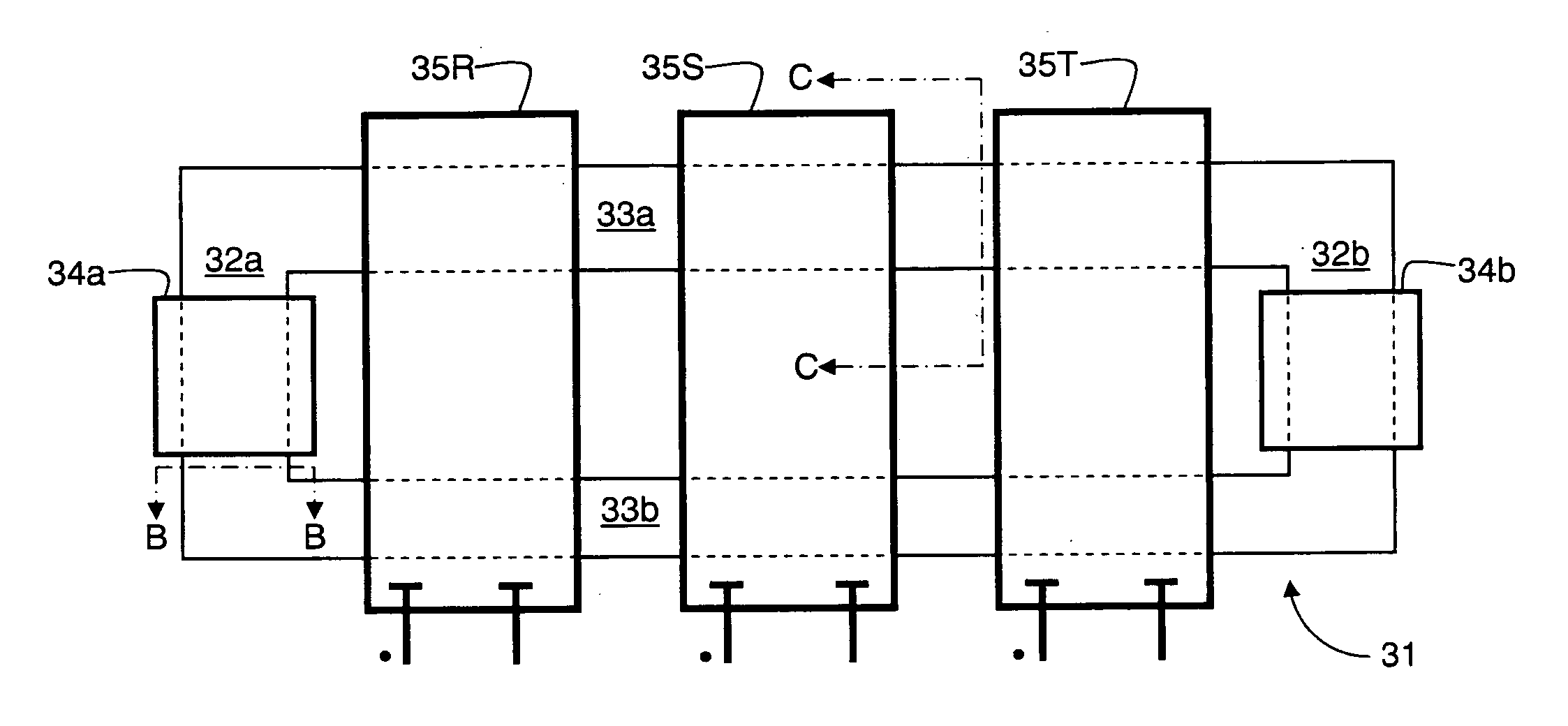
[0081]FIG. 4a shows schematically a three-phase FCL 30 having a ferromagnetic core 31 comprising “short” limbs 32a and 32b (constituting “first” limbs) and “long” limbs 33a, 33b (constituting “second” limbs). Respective bias coils 34a, 34b are wound on the short limbs 32a, 32b for maintaining the core 31 in controllable saturation. The DC bias coils 34a, 34b constitute magnetic biasing means for biasing the DC magnetic circuit into saturation at normal conditions. In this and all subsequent embodiments, this may also be achieved using permanent magnets or a combination of DC bias coils and permanent magnets.

[0082]Respective AC coils 35R, 35S, 35T, one for each phase of a 3-phase supply, are wound in mutual spatial proximity around both the long limbs 33a and 33b in a manner similar to th...


PUM


Abstract

A three-phase current limiter (30) for an alternating current system includes an AC magnetic circuit having at least one AC coil (35R1, 35S1, 35T1) for each phase of a 3-phase AC supply wound on a saturable ferromagnetic core and configured to subject respective AC coils for each phase to a common magnetic flux, and a DC magnetic circuit (34a, 34b) for biasing the AC magnetic circuit into saturation at normal conditions. In use the AC coils are connected in series with a load and during alternate half cycles of the AC supply at least one of the AC coils produces a magnetic field that opposes a magnetic field of the DC magnetic circuit. The AC coils (35R, 35S, 35T) for each phase are configured so that at least one of the AC coils exhibits unbalanced magnetic impedance relative to remaining ones of the AC coils for each phase.

Description

FIELD OF INVENTION[0001]The present invention relates to single and three-phase fault current limiters (FCL).REFERENCES[0002]Prior art references considered to be relevant as a background to the invention are listed below and their contents are incorporated herein by reference. Acknowledgement of the references herein is not to be inferred as meaning that these are in any way relevant to the patentability of the invention disclosed herein. Each reference is identified by a number enclosed in square brackets and accordingly the prior art will be referred to throughout the specification by numbers enclosed in square brackets.[0003][1] CIGRE Working Group A3.10 “Fault Current Limiters in Electrical Medium and High Voltage Systems” Technical Report, August 2003[0004][2] http: / / www.trenchgroup.com / Trench%20Group / Trench_Home / Trench_Start.html[0005][3] U.S. Pat. No. 7,330,096 “Fault Current Limiter”, M. Shah et al. Feb. 12, 2008.[0006][4] V. Rozenshtein, A. Friedman, Y. Wolfus, F. Kopansky...

Claims


Application Information

Patent Timeline
Patent Type & Authority Applications(United States)
IPC IPC(8): G05F3/06
CPCH01F3/10H01F38/023H01F29/14H02H9/02H02H9/021
Inventor WOLFUS, SHUKIYESHURUN, YOSSEFFRIEDMAN, ALEXANDERROZENSHTEIN, VLADIMIRBAR-HAIM, ZVI
Owner BAR ILAN RES & DEV
Why Eureka
Try Eureka