
Source-driving circuit, display apparatus and operation method thereof

Active Publication Date: 2012-06-21
AU OPTRONICS CORP
View PDF4 Cites 19 Cited by
  • Summary
  • Abstract
  • Description
  • Claims
  • Application Information

AI Technical Summary

Benefits of technology

[0006]The present invention also relates to a display apparatus with a high power-saving efficiency.
[0007]The present invention further relates to an operation method for a display apparatus, which can make a display panel with an HSD structure have a high power-saving efficiency.
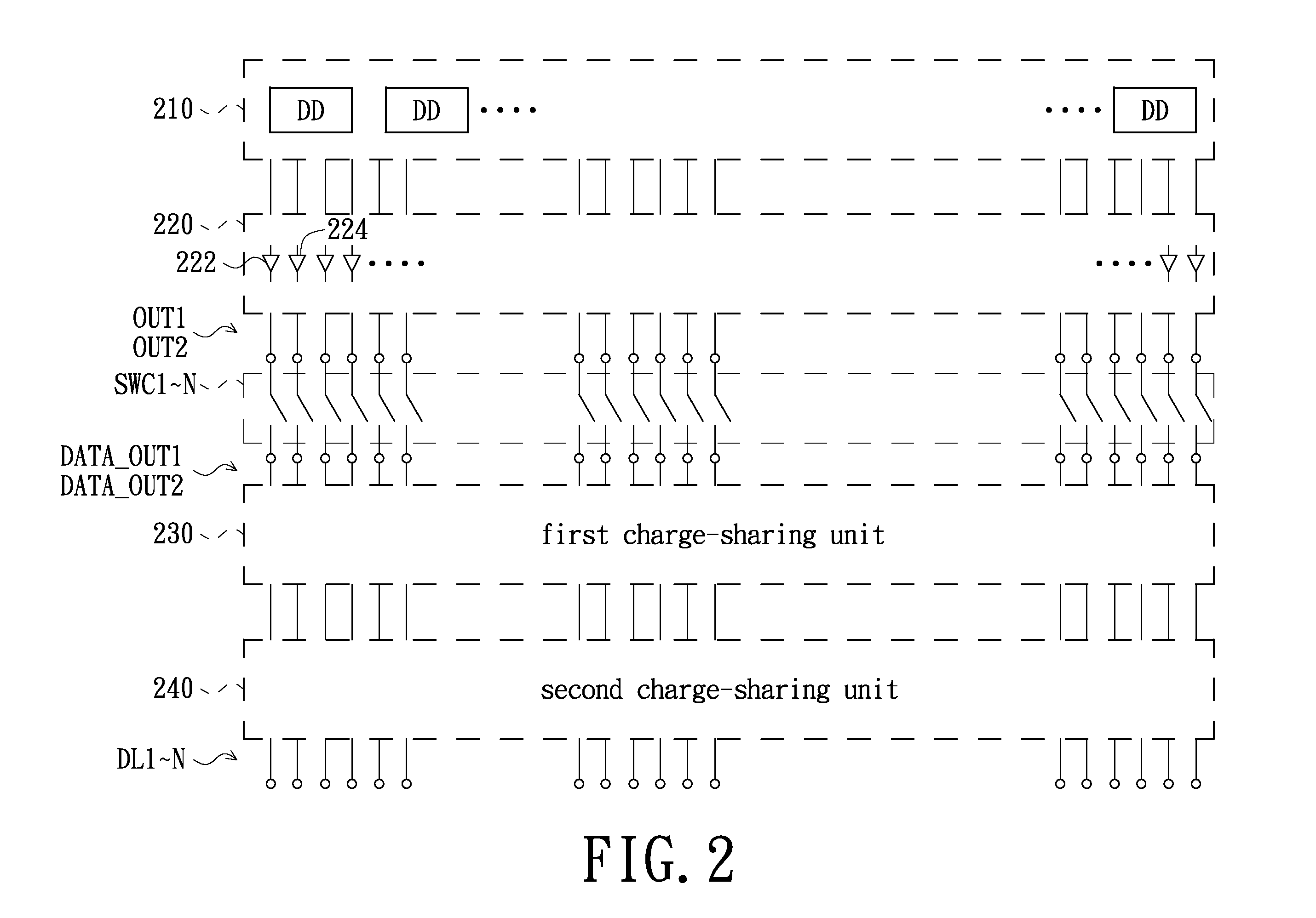
[0014]The present invention connects the first data-outputting terminals in the same group with each other and connects the second data-outputting terminals in the same group with each other when the polarity signal is in the first status. In addition, the present invention connects one of the first data-outputting terminals with a corresponding one of the second data-outputting terminals when the polarity signal is in the second status. Therefore, no matter whether the display panel operates in the line inversion mode when it displays the single-color image or operates in the dot inversion mode or the two-dot inversion mode when it displays the complementary-color image, the present invention still can share the charges, so as to reduce the power consumption.

Problems solved by technology

Therefore, the cost of the related hardware is decreased.

Method used


Image

  • Source-driving circuit, display apparatus and operation method thereof
  • Source-driving circuit, display apparatus and operation method thereof
  • Source-driving circuit, display apparatus and operation method thereof

Examples


Embodiment Construction

[0028]The present invention will now be described more specifically with reference to the following embodiments. It is to be noted that the following descriptions of preferred embodiments of this invention are presented herein for purpose of illustration and description only. It is not intended to be exhaustive or to be limited to the precise form disclosed.

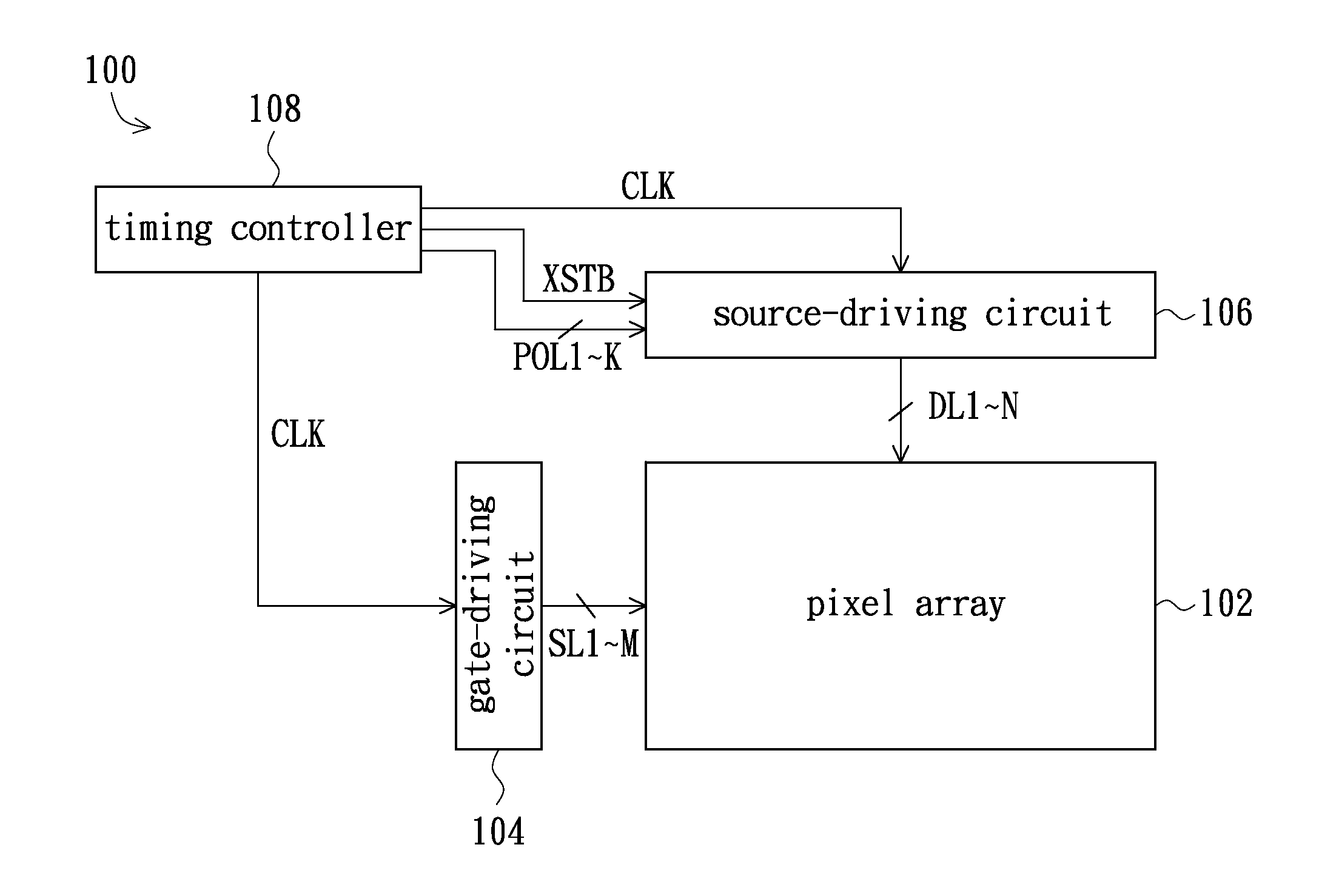
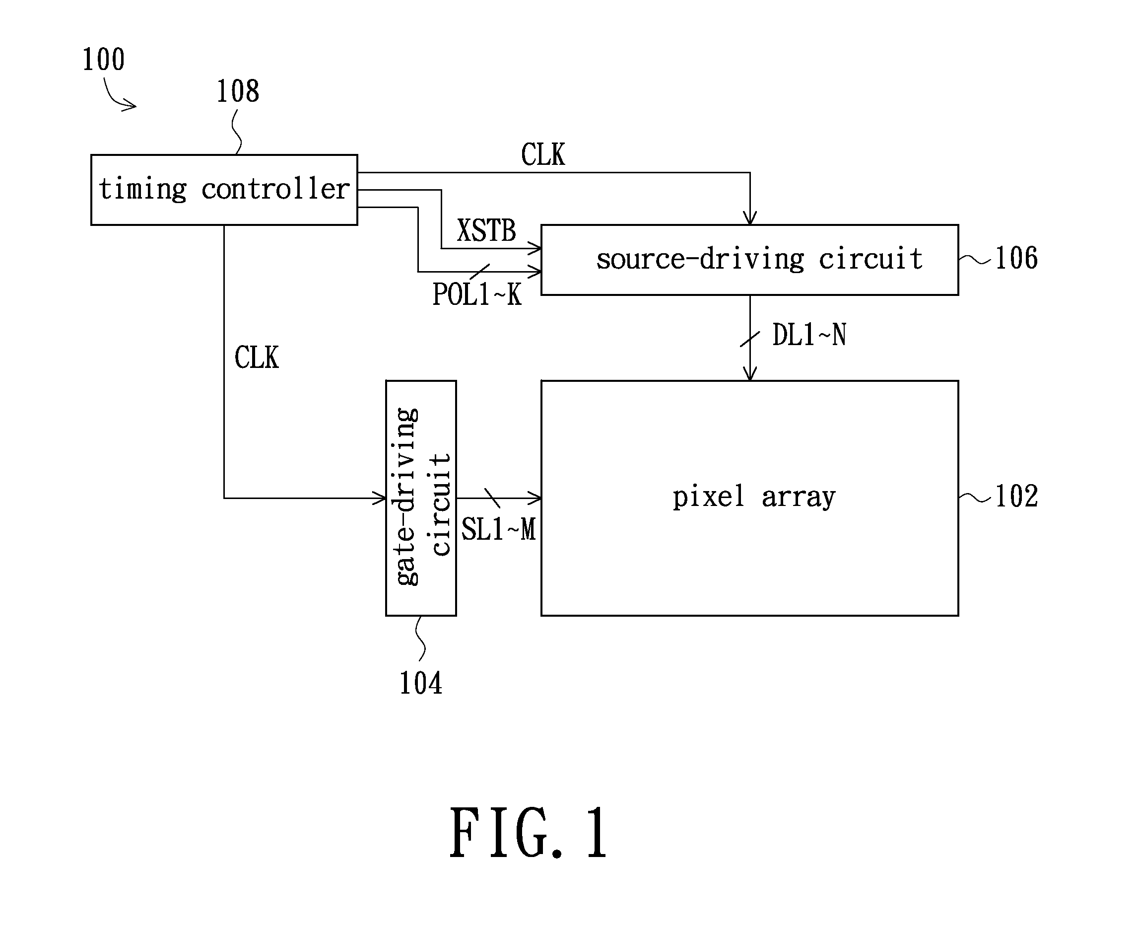
[0029]FIG. 1 shows a system block diagram of a display apparatus in accordance with an exemplary embodiment of the present invention. Referring to FIG. 1, the display apparatus 100 of the exemplary embodiment comprises a pixel array 102, a gate-driving circuit 104, a source-driving circuit 106 and a timing controller 108. The pixel array 102 is composed of a plurality of pixel units which are arranged in an array. In addition, the gate-driving circuit 104 is electrically connected to the pixel array 102 through a plurality of scan lines SL1˜M. Correspondingly, the source-driving circuit 106 is electrically connected to the pixel ...


PUM


Abstract

A source-driving circuit comprises a plurality of first and second data-outputting units, a first and a second charge-sharing units and a charge-sharing switch circuit. The first and second data-outputting units have corresponding first and second output terminals respectively for outputting data signals with a first polarity and a second polarity. The first and second charge-sharing units comprise a plurality of first and second switches respectively. Each first switch is electrically connected between each two first output terminals and each two second output terminals. Each second switch is electrically connected between one of the first outputting terminals and a corresponding one of the second outputting terminals. A charge-sharing switch circuit is electrically connected to the first and second charge-sharing units for outputting a switch signal to the first and second charge-sharing units according to a polarity signal, so as to determine the on / off statuses of the first and second switches.

Description

FIELD OF THE INVENTION[0001]The present invention relates to a power-saving technology for display apparatus, and more particularly to a power-saving technology adapted to a display apparatus with a half-source driving structure.BACKGROUND OF THE INVENTION[0002]There is a half-source driving (HSD) structure in pixel array structures of display panels. The HSD structure doubles an amount of scan lines to halve an amount of data lines. Since the amount of the data lines is halved, an amount of driving channels of a source driver is correspondingly halved. Therefore, the cost of the related hardware is decreased.[0003]Table 1 shows power consumptions of a conventional display panel with HSD structure operating in different operation modes.TABLE 1dot inversion(comprisingtwo dots inversion)line inversioncurrentpowercurrentpowerconsumptionconsumptionconsumptionconsumptionpower-savingimage mode(mA)(P)(mA)(P)efficiencyblack image43.5398.614.0129.267.6%white image19.0175.115.0138.321.0%mosai...

Claims


Application Information

Patent Timeline
IPC IPC(8): G09G5/00
CPCG09G2310/0248G09G3/3614G09G3/3688G09G2330/023G09G2310/0275G09G2310/0297G09G2310/0224
Inventor CHEN, JEN-CHIEHHSU, CHAO-CHINGLI, CHING-LIN
Owner AU OPTRONICS CORP
Learn More