
Variable wavelength interference filter, optical filter device, optical module, and electronic apparatus

Inactive Publication Date: 2012-06-21
SEIKO EPSON CORP
View PDF6 Cites 17 Cited by
  • Summary
  • Abstract
  • Description
  • Claims
  • Application Information

AI Technical Summary

Benefits of technology

[0010]An advantage of some aspects of the invention is that it provides a variable wavelength interference filter, an optical filter device, an optical module, and an electronic apparatus capable of suppressing a decrease in resolving power by employing a simple configuration even in a case where a gap dimension between reflective films changes.

Problems solved by technology

However, in a case where there is a slight tilt in the diaphragm, and the inter-electrode gap is not uniform, the smaller the inter-electrode gap becomes, the stronger an electrostatic attractive force becomes, and the tilt in the diaphragm increases.
Therefore, a sensor or the like that is used for measuring the tilted state of the diaphragm or the inter-electrode gap needs to be arranged, and accordingly, there is the problem of a complicated configuration.
In addition, since it is necessary to calculate the driving voltage to be applied to each driving electrode based on the tilted state of the diaphragm or the inter-electrode gap that has been measured, there is also a problem in that the process of controlling the driving of the electrostatic actuator is complicated.

Method used


Image

  • Variable wavelength interference filter, optical filter device, optical module, and electronic apparatus
  • Variable wavelength interference filter, optical filter device, optical module, and electronic apparatus
  • Variable wavelength interference filter, optical filter device, optical module, and electronic apparatus

Examples


first embodiment

[0053]Hereinafter, a first embodiment of the invention will be described with reference to the accompanying drawings.

Overall Configuration of Colorimetric Apparatus

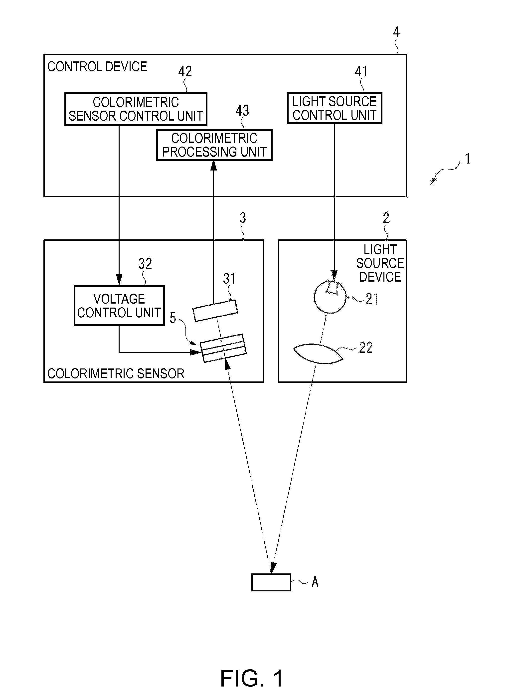
[0054]FIG. 1 is a diagram illustrating a schematic configuration of a colorimetric apparatus (electronic apparatus) according to an embodiment of the invention.

[0055]The colorimetric apparatus 1 is an electronic apparatus according to an embodiment of the invention and, as shown in FIG. 1, includes a light source device 2 that emits light onto a measurement target A, a colorimetric sensor 3 as an optical module according to an embodiment of the invention, and a control device 4 that controls the overall operation of the colorimetric apparatus 1. The colorimetric apparatus 1 is an apparatus that reflects light emitted from the light source device 2 on the measurement target A, receives reflected measurement target light by using the colorimetric sensor 3, and analyzes and measures the chromaticity of the measurement target...

second embodiment

[0131]Next, a second embodiment of the invention will be described with reference to the drawings.

[0132]In the variable wavelength interference filter 5 according to the above-described first embodiment, a configuration example is shown in which one electrostatic actuator 54 acquired by electrically connecting a plurality of the partial actuators 55 in series is disposed.

[0133]In contrast to this, in a variable wavelength interference filter 5A according to the second embodiment, a configuration is employed in which a plurality of electrostatic actuators (a first electrostatic actuator 54A and a second electrostatic actuator 54B) is disposed and is electrically connected in parallel. Hereinafter, the configuration of the variable wavelength interference filter 5A will be described in detail.

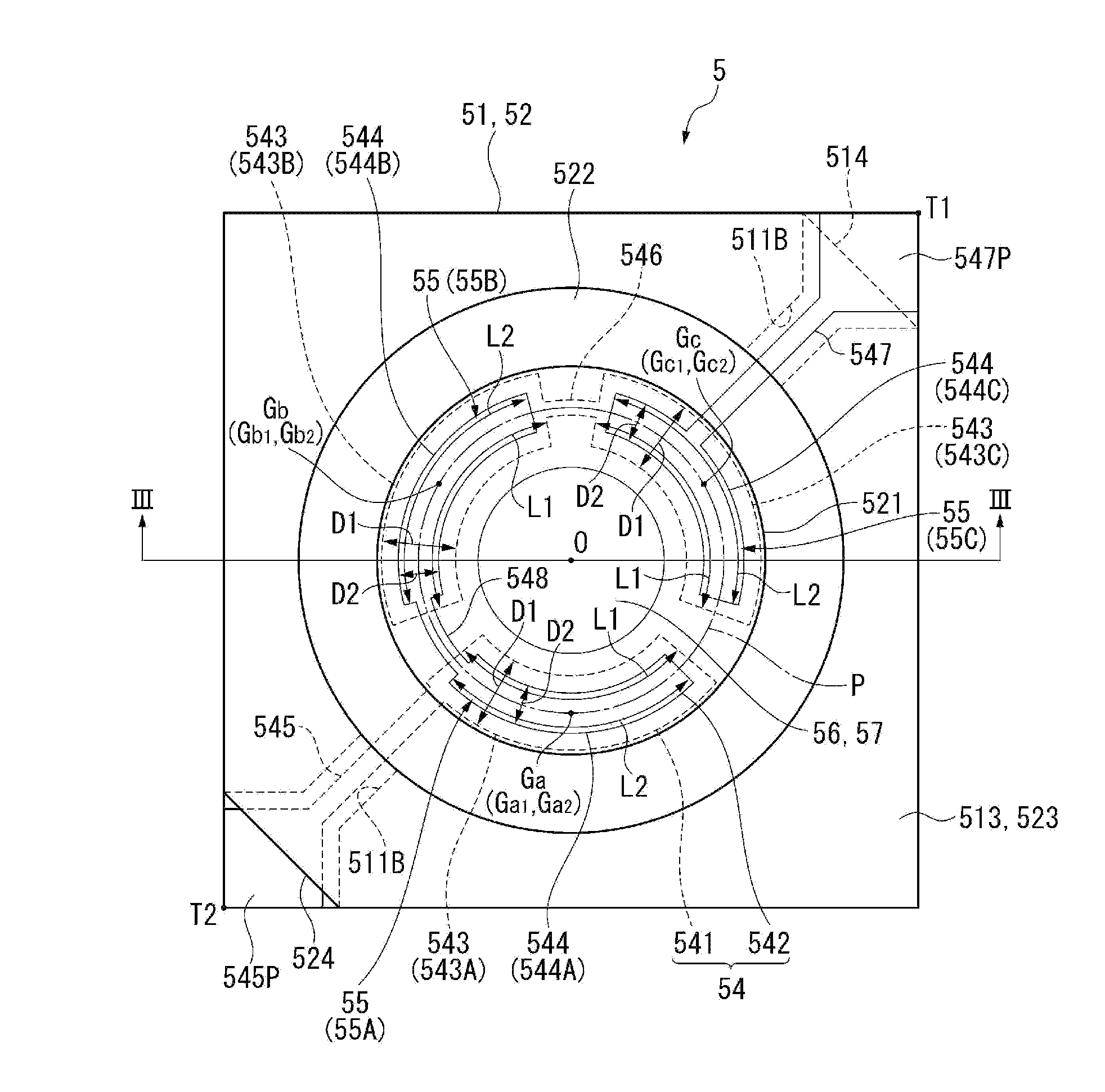
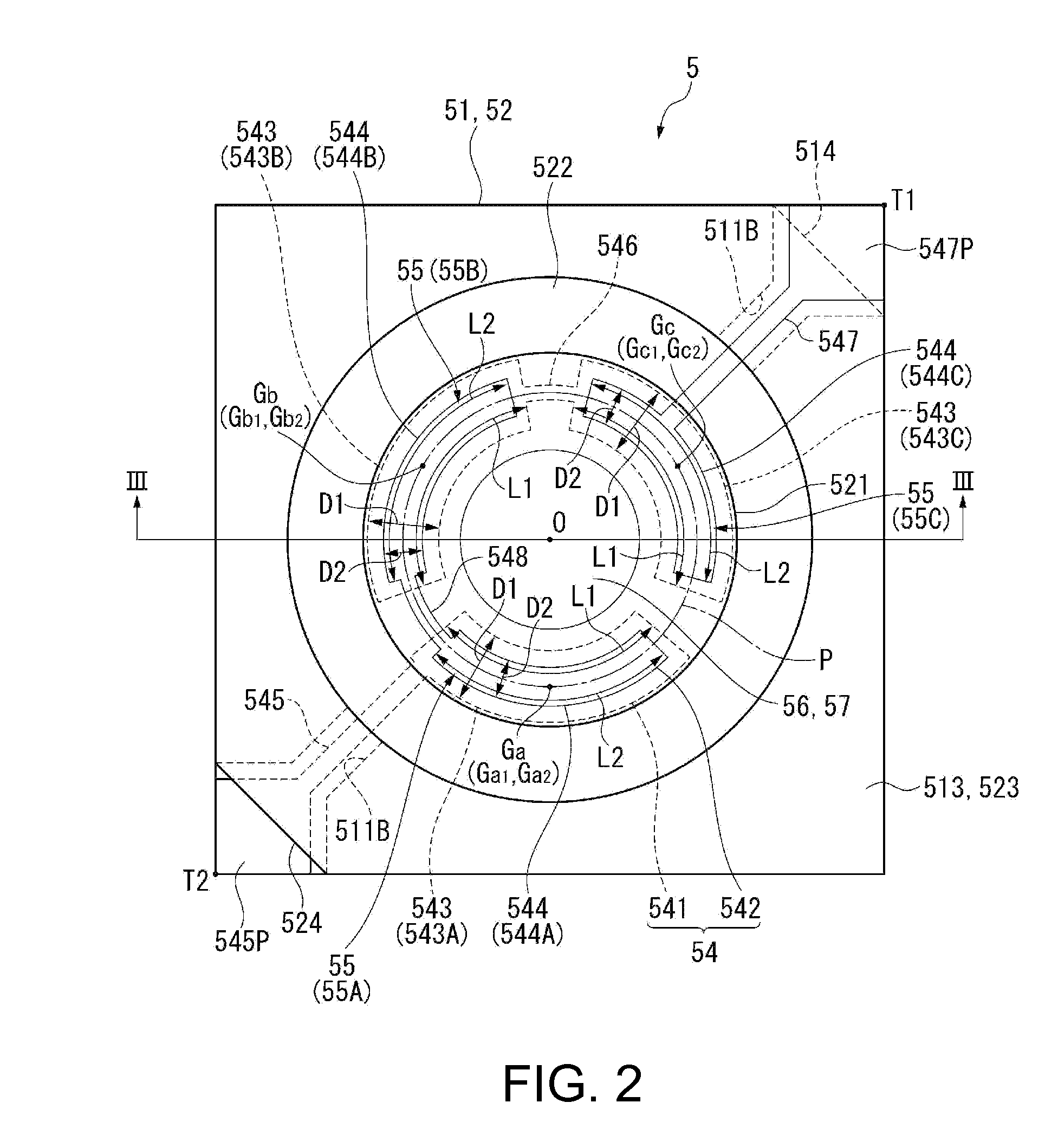
[0134]FIG. 7 is a plan view showing a schematic configuration of the variable wavelength interference filter 5A according to the second embodiment. FIG. 8 is a plan view of a fixed substrate 51 o...

third embodiment

Operation and Advantages of Third Embodiment

[0181]In the optical filter device 600 according to this embodiment, since the variable wavelength interference filter 5 is protected by the casing 601, a change in the characteristics of the variable wavelength interference filter 5 that is caused by a foreign material, gas contained in the atmosphere, or the like can be prevented, and a damage in the variable wavelength interference filter 5 that is caused by an external factor can be prevented. In addition, since the penetration of charged particles can be prevented, charging of the fixed electrode 541 or the movable electrode 542 can be prevented. Therefore, the generation of a Coulomb force according to charging can be suppressed, whereby the parallelism between the reflective films 56 and 57 can be maintained more reliably.

[0182]In addition, in a case where the variable wavelength interference filter 5, for example, manufactured in a factory, is delivered to an assembly line used for...


PUM


Abstract

A variable wavelength interference filter includes an electrostatic actuator that includes a fixed electrode and a movable electrode. The fixed electrode includes a plurality of fixed partial electrodes, the movable electrode includes a plurality of movable partial electrodes, and each partial actuator is configured by the fixed partial electrode and the movable partial electrode that face each other. The partial actuators have an equal area, have centers of gravity thereof arranged at equal angular intervals on a virtual circle having a center point of the movable portion as its center, and are electrically connected in series between partial electrodes for voltage application.

Description

BACKGROUND[0001]1. Technical Field[0002]The present invention relates to a variable wavelength interference filter, an optical filter device, an optical module, and an electronic apparatus.[0003]2. Related Art[0004]Generally, variable wavelength interference filters (optical filter elements) that extract light of a specific wavelength from light of a plurality of wavelengths are known (for example, see JP-A-2009-251105).[0005]The variable wavelength interference filter (optical filter device) disclosed in JP-A-2009-251105 includes a first substrate that includes a movable portion (first portion) and a diaphragm (second portion) supporting the movable portion and a second substrate that faces the first substrate. In addition, a movable mirror is formed on the movable portion of the first substrate, and a fixed mirror is formed on a face of the second substrate that faces the movable portion. In the first substrate and the second substrate, ring shaped electrodes are disposed so as to...

Claims


Application Information

Patent Timeline
IPC IPC(8): G02B5/28
CPCG01J3/26G02B26/001
Inventor HIROKUBO, NOZOMU
Owner SEIKO EPSON CORP
Features
  • Generate Ideas
  • Intellectual Property
  • Life Sciences
  • Materials
  • Tech Scout
  • Unparalleled Data Quality
  • Higher Quality Content
  • 60% Fewer Hallucinations
Learn More