Open-worked acoustic barrier for hybrid active/passive noise treatment

Inactive Publication Date: 2012-06-21
TECHNOFIRST
View PDF4 Cites 12 Cited by
  • Summary
  • Abstract
  • Description
  • Claims
  • Application Information

AI Technical Summary

Benefits of technology

[0055]each bar including an acoustically absorbent material on the side of the box opposite the main side for adjusting the acoustic impedance of the box and preventing the appearance of standing waves between the main side of one bar and the side opposite the main side of the adjacent bar;
[0056]the bars being disposed substantially parallel to one another side by side in such a manner that the main sides of the acoustic elements are directed towards the side opposite the main side of the adjacent bar so that the loudspeakers fire into the gap between two bars, thus constituting an open-work acoustic barrier combining a passive noise-reduction

Problems solved by technology

The drawbacks of passive acoustic reduction devices are that they are opaque visually and generally also thermally.
Anti-noise walls do not generally permit heat exchange or limit it very strongly, and they are visually opaque.
Thus the anti-noise walls generally used are relatively or totally ineffective at the predominant frequencies of the road noise spectrum SR.
Despite the improvement in screen type noise reduction devices over the last three decades, at present this technology is beginning to show its limitations and it is difficult to envisage further improvement over tradit

Method used


Image

  • Open-worked acoustic barrier for hybrid active/passive noise treatment
  • Open-worked acoustic barrier for hybrid active/passive noise treatment
  • Open-worked acoustic barrier for hybrid active/passive noise treatment

Examples


Example

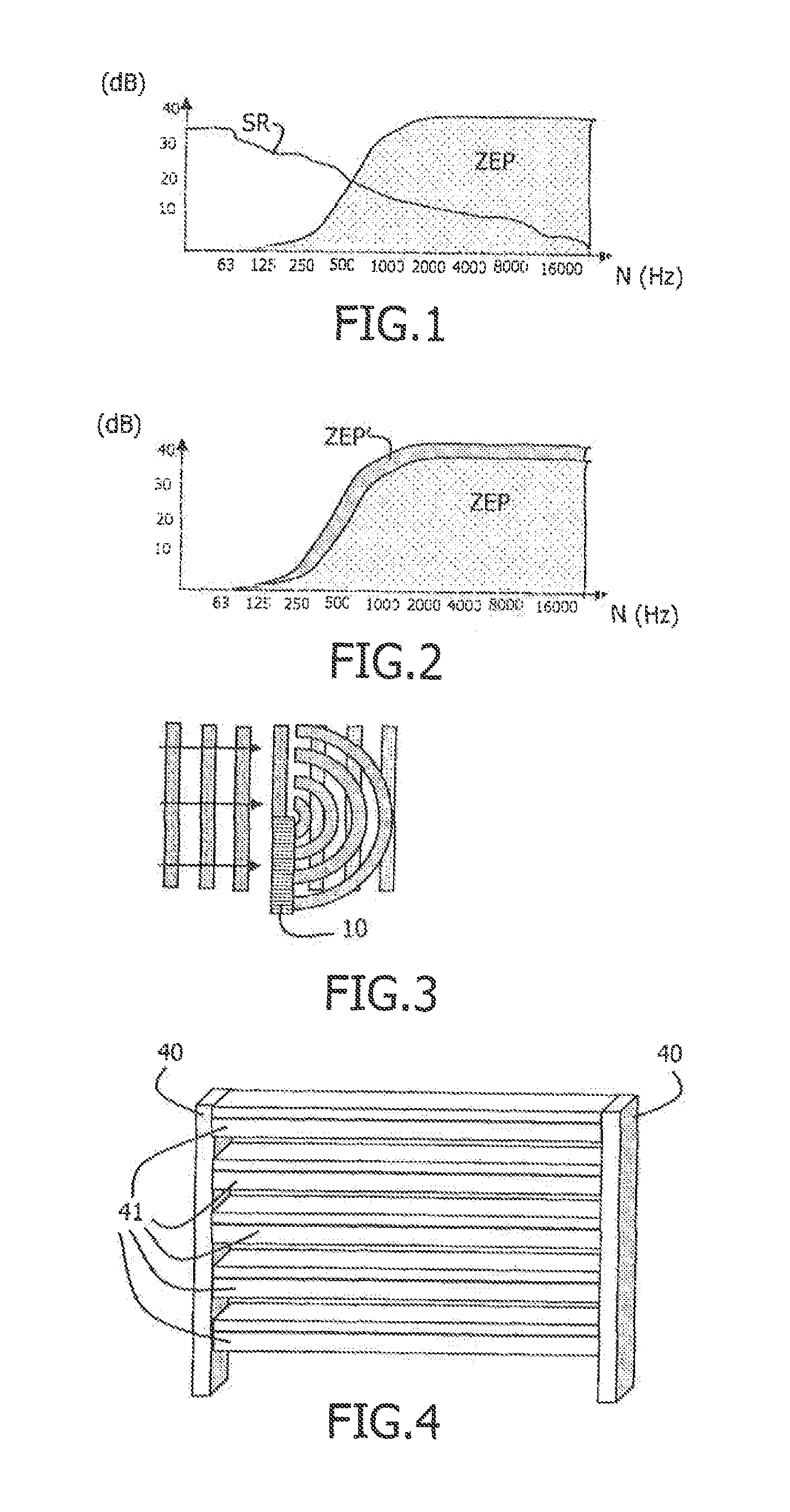
[0078]FIG. 4 shows an example of an acoustic barrier structure of the invention. Between two fixing posts 40 there is disposed a plurality of acoustic bars 41, here 5 bars (m=5). These bars 41 are linear structures separated by a distance D enabling air and light to pass through.

[0079]The acoustic bars 41 constitute passive noise reduction elements. They are therefore advantageously produced from passive acoustically absorbent materials or they include acoustically absorbent materials to enable partial acoustic isolation at high frequencies.

[0080]According to the invention, each acoustic bar 41 includes a plurality of identical and independent active systems associated physically and mechanically to produce an active acoustic effect in the gaps of thickness D between the passive acoustic bars. The plurality of acoustic bars 41 enables a combination of active and passive treatment to be obtained.

[0081]The invention thus enables treatment to be performed over a wide band, as shown in ...


PUM


Abstract

The invention relates to a method and a device for passive and active acoustic reduction, including m electro-acoustic bars (41) side by side and separated by gaps (D), thus constituting an open-work acoustic barrier combining passive and active noise-reduction. Each electro-acoustic bar (41) includes a plurality of acoustic reduction elements (70) arranged, side by side, each acoustic reduction element (70) including a microphone (62) and a loudspeaker (61) disposed inside a box (60) made of a passive acoustically absorbent material or including a passive acoustically absorbent material, the microphone (62) and the loudspeaker (61) being connected to control electronics (73) capable of receiving a measurement of the transfer function between the microphone (62) and the loudspeaker (61) and of computing a feedback control electronic filter for each acoustic reduction element (70) from the transfer function between the microphone (62) and the loudspeaker (61), and acting, within each acoustic reduction element (70), to enable the loudspeaker (61) to be electro-acoustically looped to the microphone (62) by amplifying the feedback in order to obtain real-time acoustic absorption for a predetermined, range of frequencies.

Description

BACKGROUND OF THE INVENTION[0001]The general field of the present invention is acoustic reduction devices and methods.[0002]There exist at present two large families of acoustic reduction devices: the family of passive acoustic reduction devices and the family of active acoustic reduction devices.[0003]The first family includes acoustic barriers or acoustic screens based on inert materials. For example, concrete anti-noise screens or walls have some efficacy for combating road noise. Passive acoustic reduction devices also include glazing units for windows that function as an anti-noise wall when the window is closed.[0004]The drawbacks of passive acoustic reduction devices are that they are opaque visually and generally also thermally. Anti-noise walls do not generally permit heat exchange or limit it very strongly, and they are visually opaque. Furthermore, it is known that acoustic screens generally create re-emission of sound by diffraction at the top of the screen.[0005]As for ...

Claims


Application Information

Patent Timeline
IPC IPC(8): G10K11/16
CPCG10K11/178G10K11/17817G10K11/17861G10K11/17857G10K11/17875
Inventor CARME, CHRISTIAN
Owner TECHNOFIRST
Why Eureka
Try Eureka