
Network system and method of address resolution

Active Publication Date: 2012-06-21
IND TECH RES INST
View PDF8 Cites 136 Cited by
  • Summary
  • Abstract
  • Description
  • Claims
  • Application Information

AI Technical Summary

Benefits of technology

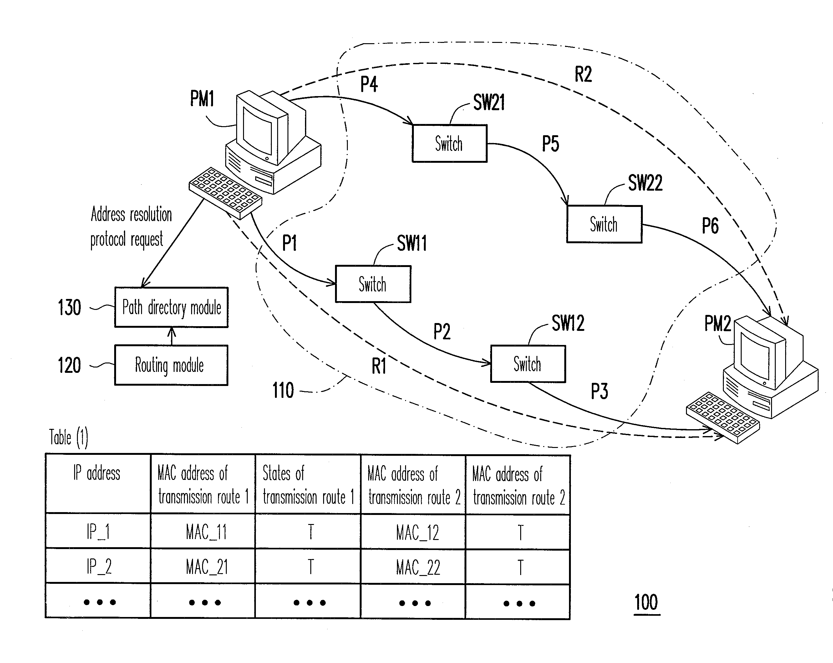
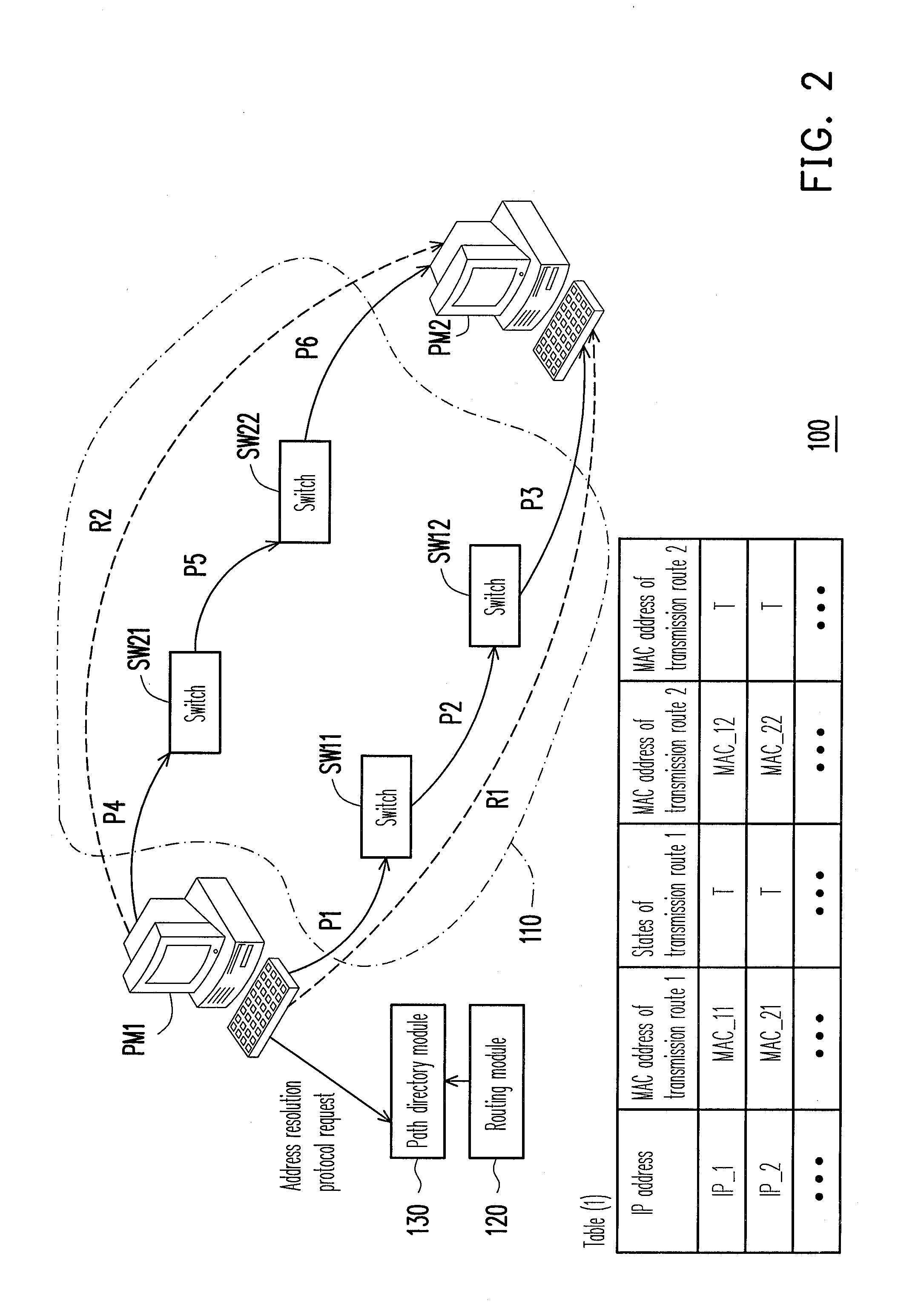
[0007]A network system is introduced herein, in which a path directory module is used to process address resolution protocol (ARP) requests of virtual machines in centralization, so as to implement a function of ARP and avoid network congestion, and when a currently used transmission route is interrupted or is excessively congested, the virtual machine can immediately use an alternate route, so as to continue data transmission without re-performing the address resolution operation.
[0008]On the other hand, a method of address resolution is introduced herein, by which a path directory module is used to process ARP requests of virtual machines in centralization, so as to implement a function of ARP and avoid network congestion, and when a currently used transmission route is interrupted or is excessively congested, the virtual machine can immediately use an alternate route, so as to continue data transmission without re-performing the address resolution operation.
[0012]According to the above descriptions, the virtual machines can direct present the ARP requests to the path directory module without broadcasting the ARP requests within a network segment, so as to implement a function of the ARP and avoid the problem of network congestion. On the other hand, the path directory module can actively notify the virtual machine to update the states of the transmission routes within a valid time of the timestamp, so that the virtual machine can immediately use an alternate route when a currently used transmission route is interrupted or excessively congested, so as to continue data transmission without re-performing the address resolution operation.

Problems solved by technology

However, a number of the servers in the same network segment of the data center can be tens of thousands, and if multiple machines simultaneously broadcast the ARP requests in the network segment, it may cause network congestion.

Method used


Image

  • Network system and method of address resolution
  • Network system and method of address resolution
  • Network system and method of address resolution

Examples


Embodiment Construction

[0022]Reference will now be made in detail to the present embodiments of the disclosure, examples of which are illustrated in the accompanying drawings. Wherever possible, the same reference numbers are used in the drawings and the description to refer to the same or like parts.

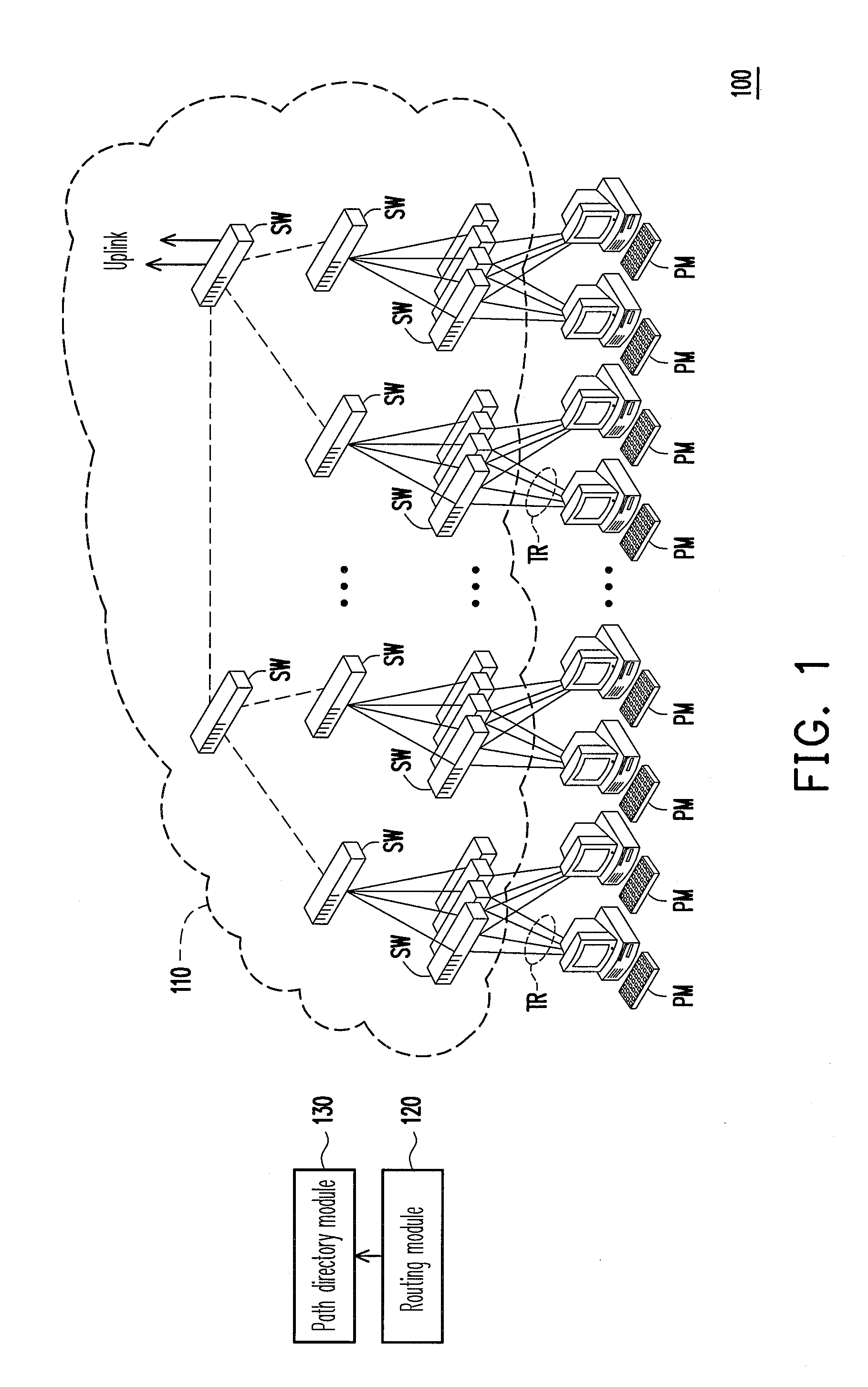
[0023]FIG. 1 is a schematic diagram illustrating a network system 100 according to a first exemplary embodiment of the disclosure. Referring to FIG. 1, the network system 100 can serve as a data center network composed of physical machines PM and virtual machines VM therein, though the network system 110 can also be applied to other types of network structures according to an actual design requirement. The network system 100 includes a network 110, the physical machines PM, a routing module 120 and a path directory module 130. In the present exemplary embodiment, network equipments (for example, switches SW, though the disclosure is not limited thereto) of layer 2 are used to construct the network 110 of a tr...


PUM


Abstract

A network system and a method of address resolution are provided. The network system includes a network, a plurality of virtual machines, a routing module and a path directory module. Each virtual machine includes an internet protocol (IP) address and N media access control (MAC) addresses, so as to connect the network through N transmission routes. The routing module detects and calculates states of the transmission routes. The path directory module receives and decodes an address resolution protocol (ARP) request presented by at least one source virtual machine to reply path information, which includes N MAC addresses corresponding to an IP address of a destination virtual machine and states of the N transmission routes. Thus, the virtual machines present the ARP request without broadcast, so that the problem of network congestion is solved.

Description

BACKGROUND[0001]1. Field of the Disclosure[0002]The disclosure relates to a network system and method of address resolution.[0003]2. Description of Related Art[0004]In domains of network service and information transmission, many corporations (for example, companies, government agencies, and research institutions, etc.) respectively construct a plurality of physical servers (for example, network servers, search servers, and mail servers, etc.) to support their remote services (or referred to as cloud services), and set up one or a plurality of virtual machines (VM) on the servers to strengthen functions thereof. In order to carry operation loads of the remote services, many corporations use multiple servers and virtual local area network (VLAN) technique to share the operation loads, so that a number of the used servers is increased. Therefore, in order to reduce an operating cost, these servers can be centralized as a data center for central management, and application programs and...

Claims


Application Information

Patent Timeline
IPC IPC(8): G06F15/173
CPCH04L29/12028H04L45/02H04L61/103H04L45/66H04L45/586
Inventor HSU, MING-CHAOSHUIEH, SHIH-YENCHIUEH, TZI-CKERCHANG, AN-NAN
Owner IND TECH RES INST
Learn More