Adaptive, scalable packet loss recovery

a packet loss and packet loss technology, applied in the field of adaptive and scalable packet loss recovery, can solve the problems of loss of data packets representing signals to be transmitted over packet data networks, inability to easily add to existing systems, and loss of existing systems, so as to facilitate signal reconstruction, prevent network congestion, and high performance of inventive systems

Inactive Publication Date: 2010-03-04
GOOGLE LLC
View PDF7 Cites 32 Cited by
  • Summary
  • Abstract
  • Description
  • Claims
  • Application Information

AI Technical Summary

Benefits of technology

[0015]The high performance of the inventive system is partly due to statistical modelling at the apparatus for decoding, which modelling facilitates signal reconstruction when the bit stream is damaged. Further, as the inventive system is entirely based on an analytic, continuous source signal model, and as the present system uses computable quantizers, real-time adaptation of the redundancy encoding during transmission is enabled. In other words, the present invention provides a communication system which can be adapted to the actual packet loss scenario of the packet data network through reception of a bit rate control signal. Thus, the system may react to, and possibly prevent, network congestion.
[0016]The present methods and apparatus are also applicable in network scenarios without packet losses to, instead of retrieval of missing parameters, increase the reconstruction quality of the coding system.

Problems solved by technology

However, existing systems are lossy, i.e., data packets representing the signals to be transmitted over the packet data networks may be lost.
A drawback of MDC-based strategies is that they cannot easily be added to existing systems and that the packet-loss robustness is integrated into the source coder.
Other existing methods for sender-based recovery of lost packets are based on adding to a primary coding system vector quantizers (VQs) that must be trained off-line, which do not provide any flexibility in the coding of the signal to be transmitted since these vector quantizers require extra computation and / or predetermined lookup tables.
A problem is that these dependencies require different estimators or the training of several statistical models for different rates and different scenarios.

Method used


Image

  • Adaptive, scalable packet loss recovery
  • Adaptive, scalable packet loss recovery
  • Adaptive, scalable packet loss recovery

Examples


Embodiment Construction

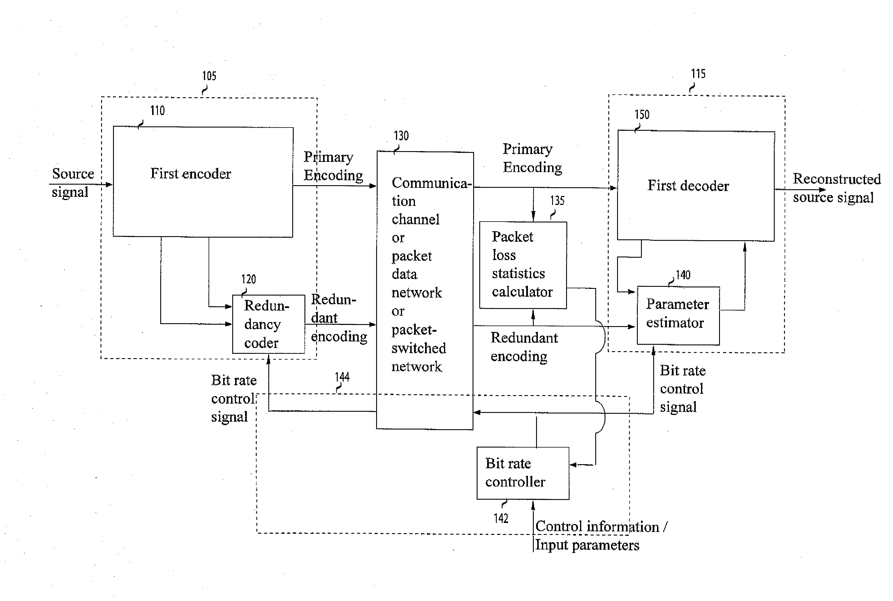
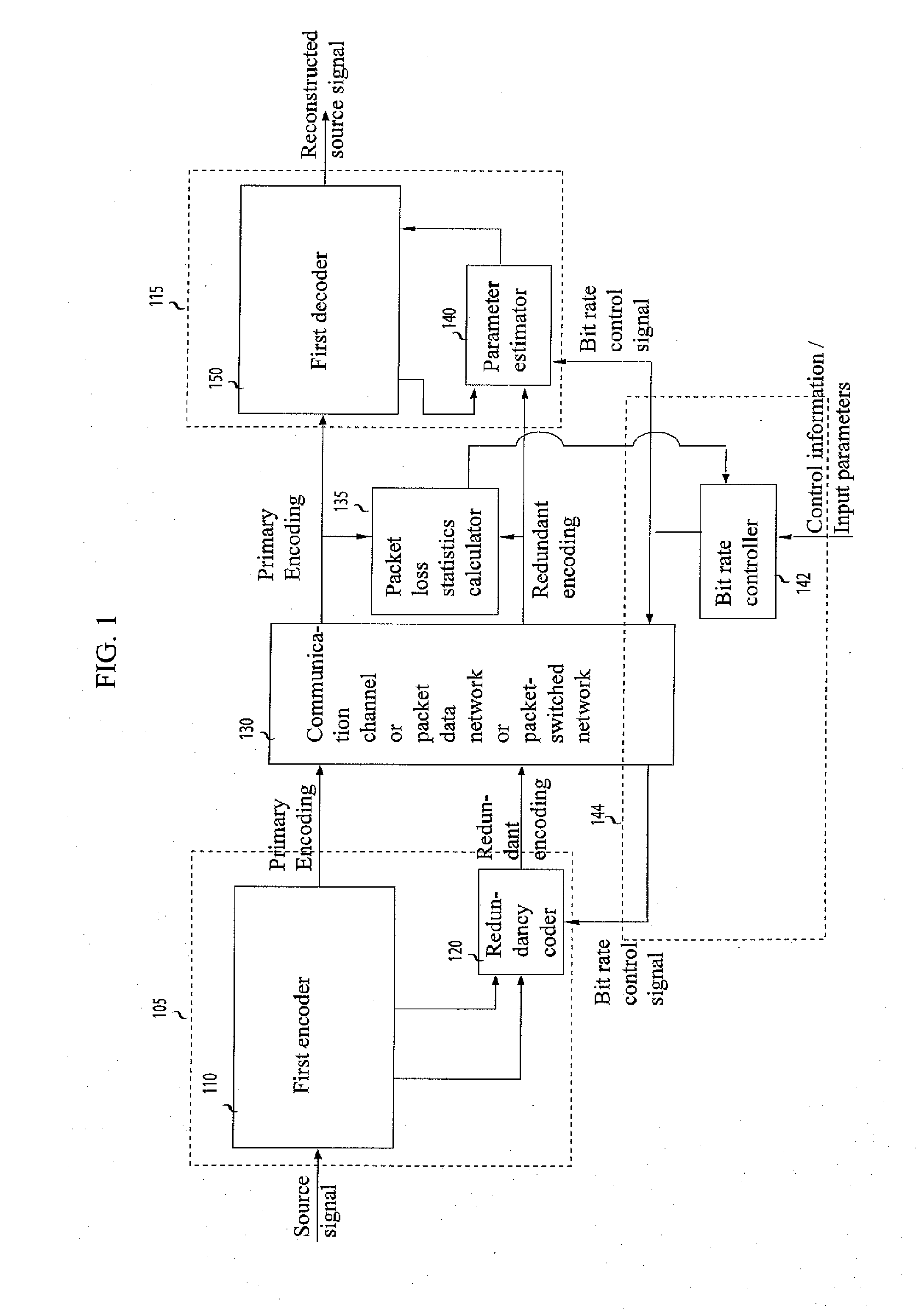
[0025]FIG. 1 shows a system from transmitting a source signal across a packet data network 130 according to an embodiment of the present invention. A source signal encoder or first coder 110 encodes a source signal and generates a primary encoding on a block-by-block basis, where a block typically is one or more time segments of the source signal. The blocks are usually but not necessarily of the same length. The source signal is generally encoded in the form of a sequence of data packets, each packet including a packet header. It is common but not necessary that the data packets are synchronous with the blocks corresponding to a particular time segment of the signal source, or a fraction thereof, or a set of segments.

[0026]In an embodiment, the primary encoding is assumed to be lossy, i.e., the reconstructed source signal generated by a corresponding source signal decoder or first decoder 150 in response to the received primary encoding is an approximation of the source signal. In ...


PUM


Abstract

A system for transmitting data packets representing a source signal across a packet data network is provided. The encoder comprises a first encoder (110) and a redundancy encoder (120). The redundancy encoding is generated with a bit rate continuously scalable, the bit rate being provided by a bit rate controller (142) that uses input from the network (130) and packet-loss rate information. At the decoder, recovery is performed by a parameter estimator based in part on information transmitted from the first encoder using information from previous and/or future blocks and in addition on redundant information. The method may be added to existing lossy source coding systems or may be used to enhance the quality of the reconstructed source signal even in scenarios without packet loss.

Description

FIELD OF THE INVENTION[0001]The present invention relates generally to a method for transmitting data packets representing a source signal across a packet data network and in particular to methods and apparatus for, on the one hand, encoding parameters representing the source signal and, on the other hand, decoding these parameters. The present invention relates in particular to encoding and decoding methods and apparatus for packet loss recovery in lossy network systems. The present invention may be applied to discrete-time signals such as multimedia signals (speech, audio signal and motion picture).BACKGROUND OF THE INVENTION[0002]Audio-visual communication over packet data networks has become more and more common. However, existing systems are lossy, i.e., data packets representing the signals to be transmitted over the packet data networks may be lost. Methods to address packet loss can be divided into two groups: receiver-based and sender-based methods. Sender-based methods, wh...

Claims


Application Information

Patent Timeline
Patent Type & Authority Applications(United States)
IPC IPC(8): H04J3/24G10L19/00G10L19/005G10L19/24
CPCG10L19/005G10L19/24H03M7/30H03M13/373H04N19/166G06F11/10H04N19/15H04N19/115H04N19/164H03M13/6312
Inventor FELDBAUER, CHRISTIANKLEIJN, WILLEM BASTIAAN
Owner GOOGLE LLC
Why Eureka
Try Eureka