Near-field scanning optical microscope

a scanning optical microscope and near-field technology, applied in the field of near-field scanning optical microscopes, can solve the problems of difficult analysis of near-field optical signals from high background noise, weak near-field light collected in the prior arts, and the relative difficulty of analyzing the near-field optical signal from the high background noise, so as to improve the focusing efficiency and improve the focusing solid angle. , the effect of enhancing the focusing

Inactive Publication Date: 2012-06-21
NAT APPLIED RES LAB
View PDF7 Cites 3 Cited by
  • Summary
  • Abstract
  • Description
  • Claims
  • Application Information

AI Technical Summary

Benefits of technology

[0014]In summation, the near-field scanning optical microscope of the present invention has one or more of the following advantages:
[0015](1) The near-field scanning optical microscope of the present invention adds a highly reflective ellipsoidal mirror installed adjacent to the probe, and the position of the ellipsoidal mirror can be adjusted mechanically, so that the probe tip of the probe can be disposed on the first focal point of the ellipsoidal mirror, and the incident light is focused around the probe tip of the probe. When the probe tip of the probe is used for scanning a surface of the testing sample, the near-field light is drawn out. After the near-field light is scattered inside the ellipsoidal mirror and reflected to pass through the second focal point, the focusing solid angle can be increased significantly, such that the focusing effect can be enhanced, and the focusing efficiency can be improved significantly. In the meantime, the shielding effect caused by the profile of the testing sample may be reduced, and such shielding effect may cause an artificial near-field optical image easily.
[0016](2) The near-field scanning optical microscope of the present invention does not come with a piezoelectric ceramic tube installed in the ellipsoidal mirror, so that the size of the ellipsoidal mirror can be reduced greatly.
[0017](3) The near-field scanning optical microscope of the present invention has not a problem that is the light is blocked by other components (such as a piezoelectric ceramic tube used for driving a testing sample), except the probe or a probe holder may block the reflected light in the ellipsoidal mirror, and thus the light-collecting performance can be improved.
[0018](4) The near-field scanning optical microscope of the present invention does not design the photomultiplier tube at the second focal point directly, but a second focusing unit is added to collect the scattered light and then transmit the scattered light to the optical fiber, and the optical fiber transmits the received scattered light into the photomultiplier tube, so that the light incident opening of the photomultiplier tube is not exposed to the outside directly, and a sudden damage to the photomultiplier tube can be prevented.

Problems solved by technology

Even though the light is transmitted to a photomultiplier tube for an electro-optical signal transformation and signal amplification, it is relatively difficult to analyze the near-field optical signal from the high background noise.
Obviously, the collected near-field light on the prior arts is very weak and difficult to be analyzed, and such technical problems require feasible solutions.

Method used


Image

  • Near-field scanning optical microscope
  • Near-field scanning optical microscope
  • Near-field scanning optical microscope

Examples


Embodiment Construction

[0024]The technical measurements taken by the present invention to achieve the foregoing objectives and effects will become apparent with the detailed description of preferred embodiments together with related drawings as follows. It is noteworthy to point out that same numerals are used for representing same respective elements in the drawings for the purpose of illustrating the present invention.

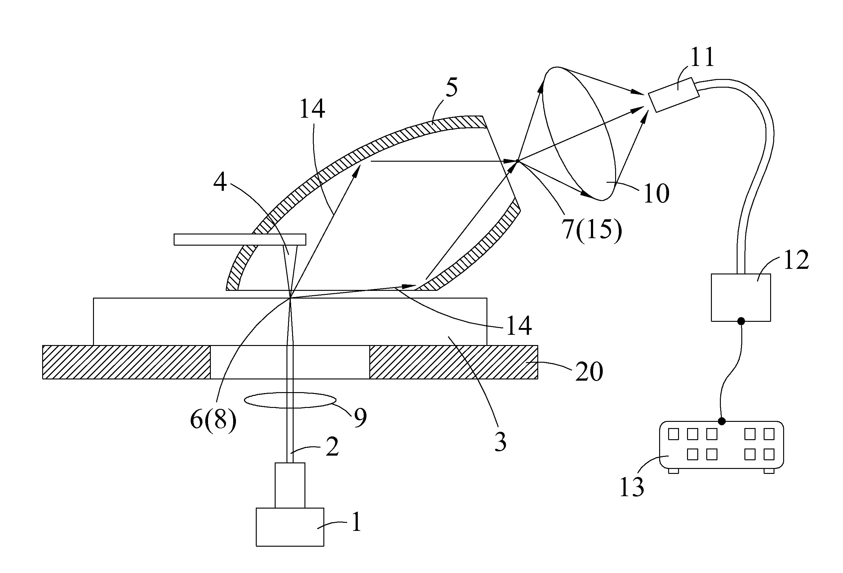
[0025]With reference to FIG. 3 for a schematic view of a near-field scanning optical microscope in accordance with a first preferred embodiment of the present invention, the microscope comprises a lighting component 1, a probe 4 and an ellipsoidal mirror 5. The lighting component 1 emits a light 2. The probe 4 is disposed on one side of a testing sample 3, and the light 2 is focused around a probe tip 8 of the probe 4 to draw out a near-field light 14. The ellipsoidal mirror 5 has a first focal point 6 and a second focal point 7, and the first focal point 6 and the probe tip 8 are disposed...


PUM


Abstract

A near-field scanning optical microscope is disclosed. The microscope includes a lighting component, a probe and an ellipsoidal mirror. The lighting component emits a light. The probe is disposed on one side of a testing sample, and the light is focused around a probe tip to draw the near-field light out. The ellipsoidal mirror has a first focal point and a second focal point, and the first focal point and the probe tip are disposed at the corresponding positions, and the near-field light drawn out from the probe tip is scattered from the first focal point inside the ellipsoidal mirror, and reflected and passed through the second focal point.

Description

BACKGROUND OF THE INVENTION[0001]1. Field of the Invention[0002]The present invention discloses a near-field scanning optical microscope. The microscope includes a lighting component, a probe and an ellipsoidal mirror. The lighting component emits a light. The probe is disposed on one side of a testing sample, and the light. is focused around a probe tip to draw the near-field light out. The ellipsoidal mirror has a first focal point and a second focal point, and the first focal point and the probe tip are disposed at the corresponding positions respectively, and the near-field light drawn out from the probe tip is scattered from the first focal point inside the ellipsoidal minor, and reflected and passed through the second focal point.[0003]2. Description of the Related Art[0004]With reference to FIG. 1 for a conventional measuring technique by using a near-field microscope for a near-field optical scanning, FIGS. 1(a), 1(b) and 1(c) show an aperture probe. Although a smaller apert...

Claims


Application Information

Patent Timeline
Patent Type & Authority Applications(United States)
IPC IPC(8): G01Q60/18
CPCB82Y20/00G01Q60/22B82Y35/00
Inventor CHEN, CHIH-WENSZE, JYH-ROUTSAI, DIN-PINGCHEN, FONG-ZHI
Owner NAT APPLIED RES LAB
Why Eureka
Try Eureka