Vacuum control valve and vacuum control system

a vacuum control valve and control system technology, applied in the direction of valve operating means/releasing devices, fluid dynamics, functional valve types, etc., can solve the problems of uneven gas supply, uneven supply, uneven supply, etc., and achieve the effect of improving the control capability of the vacuum control system

Active Publication Date: 2012-06-28
CKD
View PDF11 Cites 6 Cited by
  • Summary
  • Abstract
  • Description
  • Claims
  • Application Information

AI Technical Summary

Benefits of technology

[0009]An object of the present invention is to provide a vacuum control valve that is capable of improving a control capability of a vacuum control system.
[0011]With the first aspect of the present invention, the control is performed by a vacuum control valve in which the gap between the outer peripheral surface of the piston and the inner peripheral surface of the cylinder is tightly sealed by a sealing film-form elastic body while following an operation of the piston. The vacuum control valve is configured in this manner has a low hysteresis characteristic, and therefore a control capability of the vacuum control system can be improved dramatically.

Problems solved by technology

When the center of the opening portion moves in this manner, bias is generated between gas flows FL1, FL2 through the interior of the vacuum chamber 710, leading to unevenness in the gas supply such as the formation of a stagnation region in which the gas supply is disrupted, for example.
Moreover, in another configuration where the gas is supplied from one side of the wafer W and discharged from the other side of the wafer W, this unevenness in the gas supply occurs as a reduction in a concentration of the thin film forming element in the vicinity of the exhaust side of the wafer W. This bias in the gas supply generates unevenness in a film thickness on the processing surface Ws, and this phenomenon becomes gradually more apparent with increases in the precision and density of products such as that described above.

Method used


Image

  • Vacuum control valve and vacuum control system
  • Vacuum control valve and vacuum control system
  • Vacuum control valve and vacuum control system

Examples


first embodiment

(A. Configuration of Vacuum Control System )

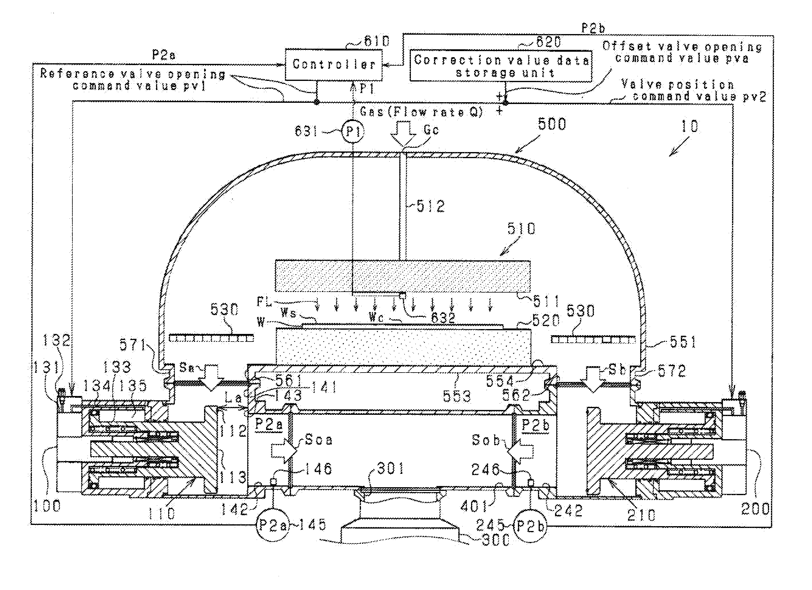
[0038]FIG. 3 is a sectional view showing the configuration of a vacuum control system 10 according to the first embodiment. FIG. 4 is a plan view of the vacuum control system 10 according to the first embodiment. The vacuum control system 10 controls a flow of gas supplied to a vacuum chamber 500 in which a chemical vapor deposition (CVD) process is performed. The vacuum control system 10 includes two vacuum control valves 100, 200 and a single turbo-molecular pump 300. The vacuum control valve 100 is connected between a gas discharge port 561 of the vacuum chamber 500 and the turbo-molecular pump 300. The vacuum control valve 200 is connected between a gas discharge port 562 of the vacuum chamber 500 and the turbo-molecular pump 300. In this embodiment, the two vacuum control valves 100, 200 have identical configurations. A dry pump (not shown) is connected to the turbo-molecular pump 300 in series therewith.

[0039]The vacuum chamber 500 i...


PUM

PropertyMeasurementUnit
vacuum pressureaaaaaaaaaa
distanceaaaaaaaaaa
pressureaaaaaaaaaa

Abstract

The invention provides a vacuum control valve configured to control the vacuum pressure in the vacuum chamber. The vacuum control valve includes a control valve main body, an operation unit, a cylinder, a biasing unit, and a bellofram. The operation unit and the cylinder include a valve opening manipulation chamber and a shutoff load generation chamber. The shutoff load generation chamber is configured to have a common axial center line with the valve opening manipulation chamber and to generate a load applied to the operation unit in a direction for reducing the lift in accordance with a supply of the working fluid. And the shutoff load generation chamber may be formed in an interior of the rod.

Description

CROSS-REFERENCE TO RELATED APPLICATIONS[0001]This application is a Divisional Application of U.S. patent application Ser. No. 12 / 986,119, filed on Jan. 6, 2011 which claims priority of Japanese Patent Application No. 2010-007104 filed on Jan. 15, 2010, Japanese Patent Application No. 2010-113694 filed on May 17, 2010 and Japanese Patent Application No. 2010-113695 filed on May 17, 2010, all of which, including the US application, are hereby incorporated by reference.BACKGROUND OF THE INVENTION[0002]1. Field of the Invention[0003]The present invention relates to a technique for controlling the behavior of a fluid in a vacuum chamber used in a manufacturing process with a vacuum control valve.[0004]2. Description of the Related Art[0005]A semiconductor manufacturing process includes a process of disposing a wafer W inside a vacuum chamber 710 (see FIGS. 1, 2) and exposing a processing surface Ws of the wafer W to a processing gas (also referred to simply as gas in this specification),...

Claims


Application Information

Patent Timeline
Patent Type & Authority Applications(United States)
IPC IPC(8): F15D1/00F16K1/00
CPCH01L21/67253H01L21/6719C23C16/52F16K51/02Y10T137/2562Y10T137/7761Y10T137/2572Y10T137/7758Y10T137/0318Y10T137/777
Inventor ITAFUJI, HIROSHIKOUKETSU, MASAYUKI
Owner CKD
Why Eureka
Try Eureka