
Organ viability

a kidney and organ technology, applied in the field of organ viability, can solve the problems of affecting the hemodynamics and metabolism of local tissues, no objective, quantitative, non-invasive method to determine whether a kidney is viable, and unreliable and/or undesirable effects

Active Publication Date: 2012-06-28
QUALITY ELECTRODYNAMICS
View PDF1 Cites 0 Cited by
  • Summary
  • Abstract
  • Description
  • Claims
  • Application Information

AI Technical Summary

Problems solved by technology

Unfortunately, conventionally, there has been no objective, quantitative, non-invasive method to determine whether a kidney is viable.
Microdialysis and other invasive approaches can alter local tissue hemodynamics and metabolism and lead to unreliable and / or undesirable results.
Unfortunately, in addition to being invasive and damaging cells, the biopsy may lead to potentially misleading results.
For example, a biopsy may incorrectly report that a kidney is not viable because data may be acquired from cells damaged by the biopsy.
Additionally, a kidney may be identified as being viable by the biopsy but then incur additional ischemic damage during transport that makes the kidney become non-viable.
However, none of this research has lead to a surgically relevant test for viability that can be performed in a timely manner in the multiplicity of locations where kidneys are harvested and transplanted.
Therefore, non-viable kidneys continue to be transported and even, in some cases, transplanted.
Similar research and issues exist for other organs.
Simply harvesting more kidneys would not solve the kidney transplant issue because once a kidney is harvested, it must be transported.
The drive module provides positive O2 pressure and is not suited for placement in the bore of a conventional MRI apparatus.

Method used


Image

  • Organ viability
  • Organ viability
  • Organ viability

Examples


Embodiment Construction

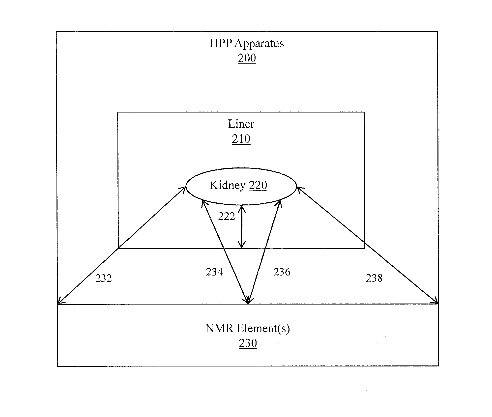
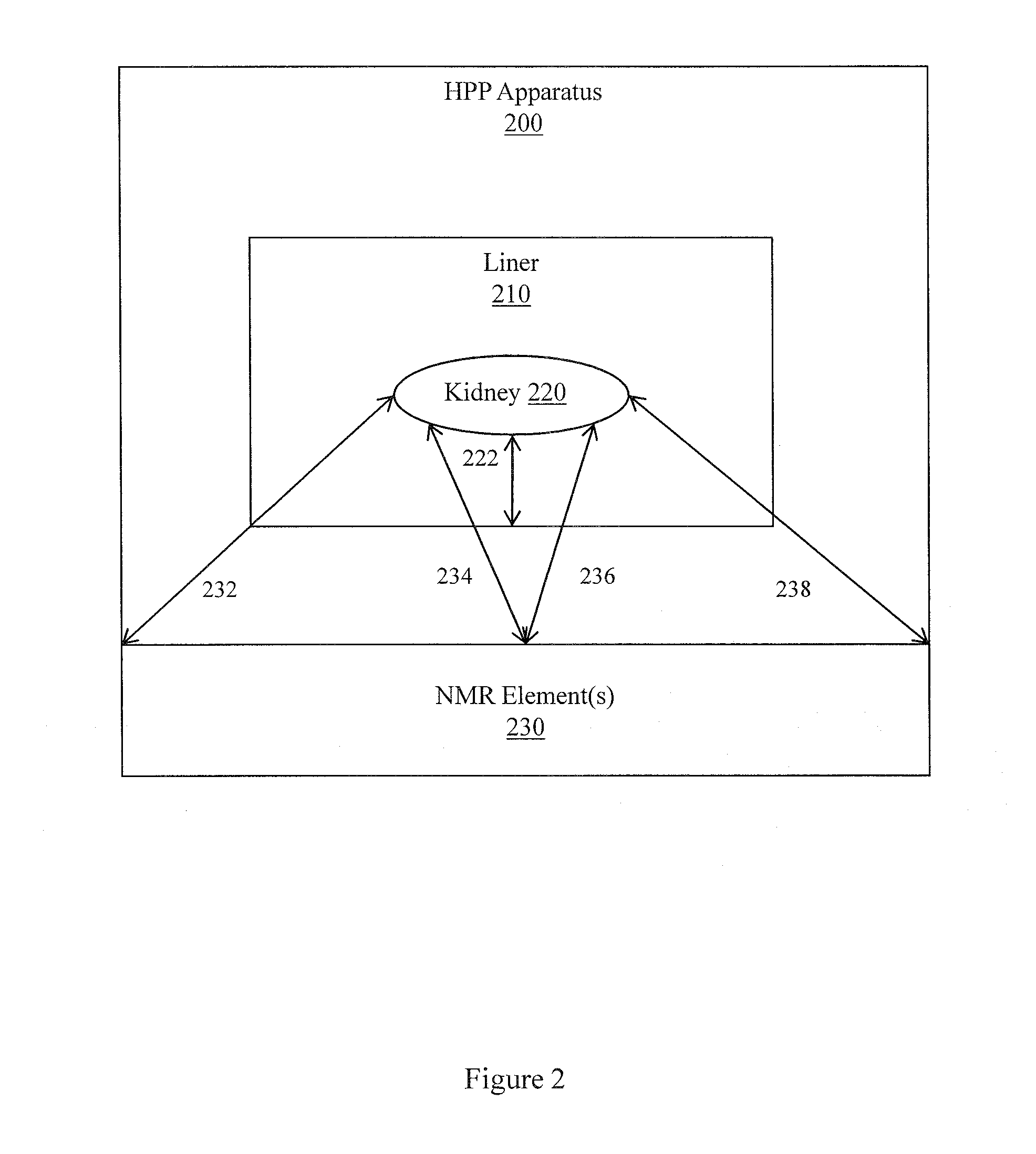
[0016]Described herein are example apparatuses and methods associated with a dedicated MR apparatus configured to interact with an HPP apparatus that is integrated with at least one MR specific element (e.g., coil, magnet). In one embodiment, the dedicated MR apparatus performs MRS on an organ in the HPP apparatus using a high field (e.g., 3T) with a conventional pulse sequence. In another embodiment, the dedicated MR apparatus performs MRS on an organ in the HPP apparatus using a lower field with an organ viability specific pulse sequence (OVSPS) that acquires organ viability specific data in a shorter period of time than conventional systems.

[0017]More generally, described herein are example apparatuses and methods associated with improving workflow and accuracy in determining organ viability. Example apparatuses integrate one or more MR elements (e.g., coil, magnet) into an organ holding container. Example dedicated apparatuses are configured to work with the integrated container...


PUM


Abstract

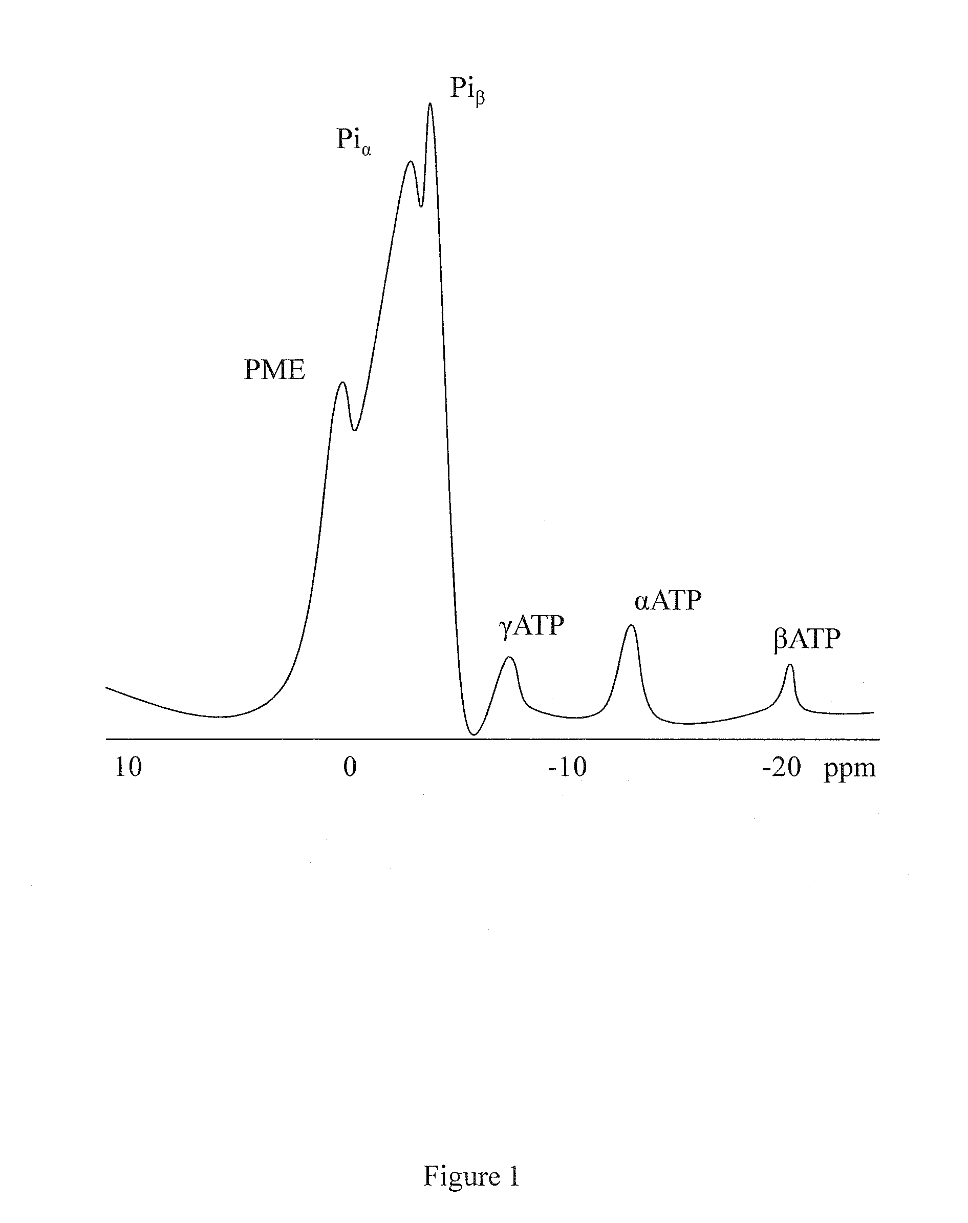
Apparatuses, methods, and other embodiments associated with determining organ viability are described. According to one embodiment, an apparatus includes logic configured to apply nuclear magnetic resonance (NMR) energy to a kidney positioned in a hypothermic pulsative perfusion (HPP) apparatus. The NMR energy is produced according to an MRS 31P specific pulse sequence. The HPP apparatus has an integrated RF coil. The HPP may also have an integrated magnet. The RF coil is positioned and oriented to facilitate optimizing 31P MRS of the kidney. The apparatus also includes logic configured to receive spectrum data from the kidney. The spectrum data is produced in response to applying the NMR energy to the kidney. The apparatus also includes logic configured to provide objective, quantitative kidney viability data (e.g., PME / Pi, ATP / ADP) from the spectrum data. More generally, MRI / MRS compatible HPP apparatuses are configured to interact with dedicated NMR spectroscopy apparatuses.

Description

BACKGROUND[0001]Organ transplants require viable organs. For example, a successful kidney transplant requires a viable kidney. Currently, the number of patients waiting for kidneys far exceeds the number of kidneys available for donation. Similar conditions exist for other organs. Thus, attempts have been made to expand the donor pool for kidneys. For example, in addition to healthy volunteers (e.g., twin brother), kidneys may be harvested from brain-dead donors and even from heart-dead donors. Unfortunately, conventionally, there has been no objective, quantitative, non-invasive method to determine whether a kidney is viable. Visual observation of a kidney while being perfused is purely subjective and thus sub-optimal. Microdialysis and other invasive approaches can alter local tissue hemodynamics and metabolism and lead to unreliable and / or undesirable results. One conventional viability test involved performing a harvest-time biopsy. Unfortunately, in addition to being invasive a...

Claims


Application Information

Patent Timeline
IPC IPC(8): G01R33/44G01R33/48
CPCG01R33/30G01R33/465G01R33/3635
Inventor FUJITA, HIROYUKIPATRICK, JOHN L.RICHARD, RONALD B.
Owner QUALITY ELECTRODYNAMICS
Learn More