Time and Power Based Wireless Location System

Active Publication Date: 2012-06-28
TRUE POSITION INC
View PDF3 Cites 28 Cited by
  • Summary
  • Abstract
  • Description
  • Claims
  • Application Information

AI Technical Summary

Benefits of technology

[0017]Disclosed herein is a method for processing readily available radio network, timing and power information about cellular networks and typical measurements made by the mobile device and network. A prob

Problems solved by technology

The limitation of only six neighbor cell RxLevel measurements present in the NMR l

Method used


Image

  • Time and Power Based Wireless Location System
  • Time and Power Based Wireless Location System
  • Time and Power Based Wireless Location System

Examples


Embodiment Construction

[0038]We will now describe illustrative embodiments of the present invention. First, we provide a detailed overview of the problem and then a more detailed description of example embodiments of the present invention.

A. Overview

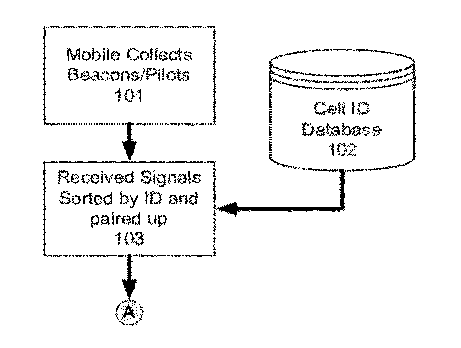
[0039]Determining the location of a transmitter is commonly achieved by measuring characteristics of the transmitter's signal at a number of known locations. Typical characteristics measured include signal power (RSSI), time-of-arrival (TOA), angle-of-arrival (AoA), or any combination thereof. GSM mobiles may be geolocated in sectored GSM networks with medium accuracy using information about the network that is readily available and measurements typically made by the Mobile Station (MS) in the network during course of supporting mobility.

[0040]The readily available network information includes the geographic location of the cell sites, the spatial response of the sectored antennas including their geographic and downtilt orientation, and the sector identifiers ...


PUM


Abstract

Disclosed is a method for processing readily available radio network, timing and power information about cellular networks and typical measurements made by the mobile device and network. A probabilistic method is disclosed that uses both time (i.e., range) and power differences with known downlink transmitter antenna characteristics to locate mobiles with accuracy better than cell-ID with ranging, with high capacity, and without the need for field calibration.

Description

TECHNICAL FIELD[0001]The present invention relates generally to methods and apparatus for locating wireless devices, also called mobile stations (MS), such as those used in analog or digital cellular systems, personal communications systems (PCS), enhanced specialized mobile radios (ESMRs), and other types of wireless communications systems. More particularly, but not exclusively, the present invention relates to the position of mobile devices using pre-existing wireless infrastructure data.BACKGROUND[0002]A wireless communications network (WCN) manages mobility of a wireless mobile device by collecting radio information about the network. From the advent of location-based services, this radio information has been used to provide low and medium accuracy location estimates.[0003]In non-softhandoff systems, the location of every active mobile in the network is known to the nearest serving cell and sector. The identification of the serving cell and serving sector can be converted to a ...

Claims


Application Information

Patent Timeline
IPC IPC(8): H04W4/00H04W4/02
CPCG01S5/08H04W4/02H04W64/00
Inventor SOMA, PITCHAIAHBULL, JEFFREY F.MIA, RASHIDUS S.BOYER, PETE A.
Owner TRUE POSITION INC
Why Eureka
Try Eureka