Stabilization device for stabilizing vertebrae or bone parts

a stabilizing device and vertebrae technology, applied in the direction of internal osteosynthesis, fasteners, medical science, etc., can solve the problems of increasing costs and rendering spinal surgery more complicated for surgeons or practitioners, and achieve the effect of improving

Active Publication Date: 2012-06-28
BIEDERMANN TECH GMBH & CO KG
View PDF2 Cites 21 Cited by
  • Summary
  • Abstract
  • Description
  • Claims
  • Application Information

AI Technical Summary

Benefits of technology

[0009]It is an object of the invention to provide a stabilization device for ver

Problems solved by technology

The need for these different bone anchoring devices increases costs and

Method used


Image

  • Stabilization device for stabilizing vertebrae or bone parts
  • Stabilization device for stabilizing vertebrae or bone parts
  • Stabilization device for stabilizing vertebrae or bone parts

Examples


first embodiment

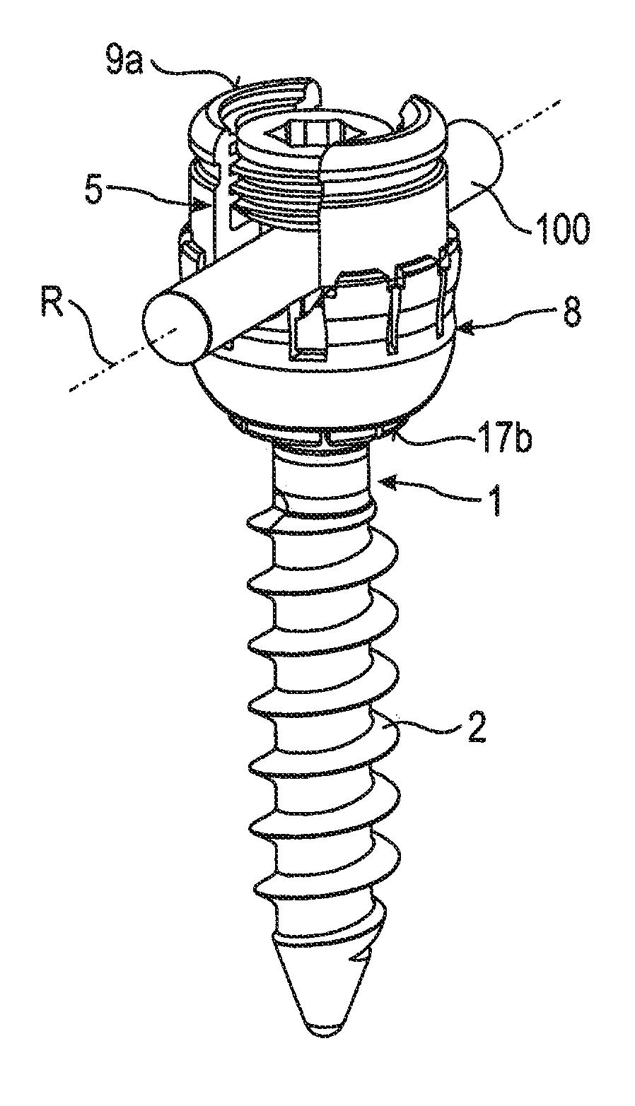
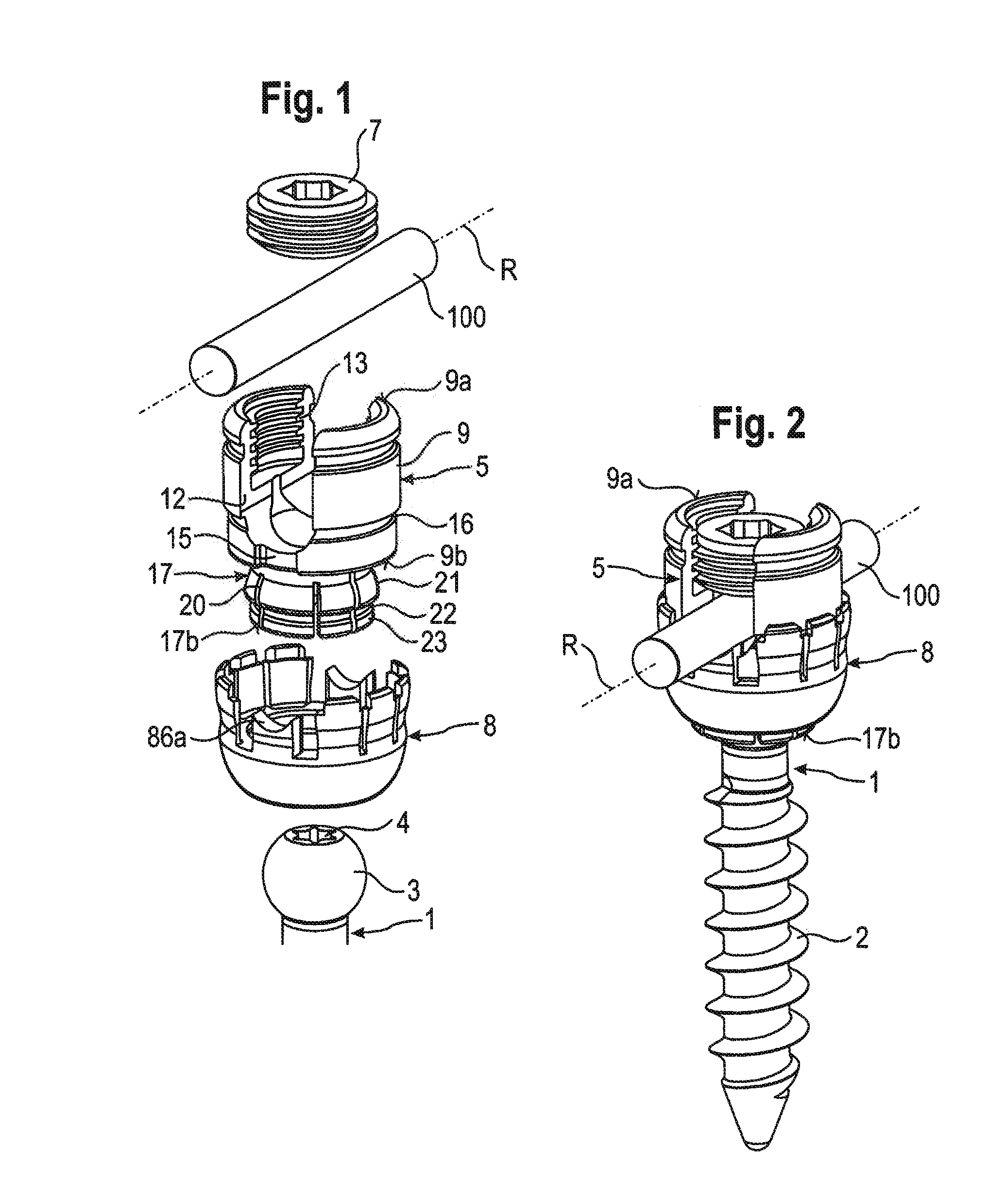
[0031]As shown in FIGS. 1 and 2, a stabilization device includes a bone anchoring element 1 in the form of a bone screw having a threaded shaft 2 and a head 3 with a curved surface portion. In this embodiment, the head 3 is spherical segment-shaped. The head 3 has a recess 4 for engagement with a tool. The stabilization device also includes a receiving part 5 for receiving a first rod 100 to connect the first rod 100 to the bone anchoring element 1. Further, a fixation element 7, in the form of an inner screw in this embodiment, is provided for fixing the rod 100 in the receiving part 5. The stabilization device also includes a locking ring 8 for locking the head 3 in the receiving part 5. At least one further rod (not shown) is provided that has a diameter different from a diameter of the first rod 100. The rods may have circular cross-sections. Also, the rods may have substantially smooth surfaces.

[0032]The receiving part 5 will be explained with reference to FIGS. 1 to 4. The re...

second embodiment

[0053]As shown in FIG. 13, in a modified second embodiment, a bottom of the V-shaped groove has inwardly curved portions 860a′ and straight sidewalls 861a′.

[0054]In a further modification, as shown in FIGS. 14a to 14c, a V-shaped groove additionally includes straight side walls 863a′.

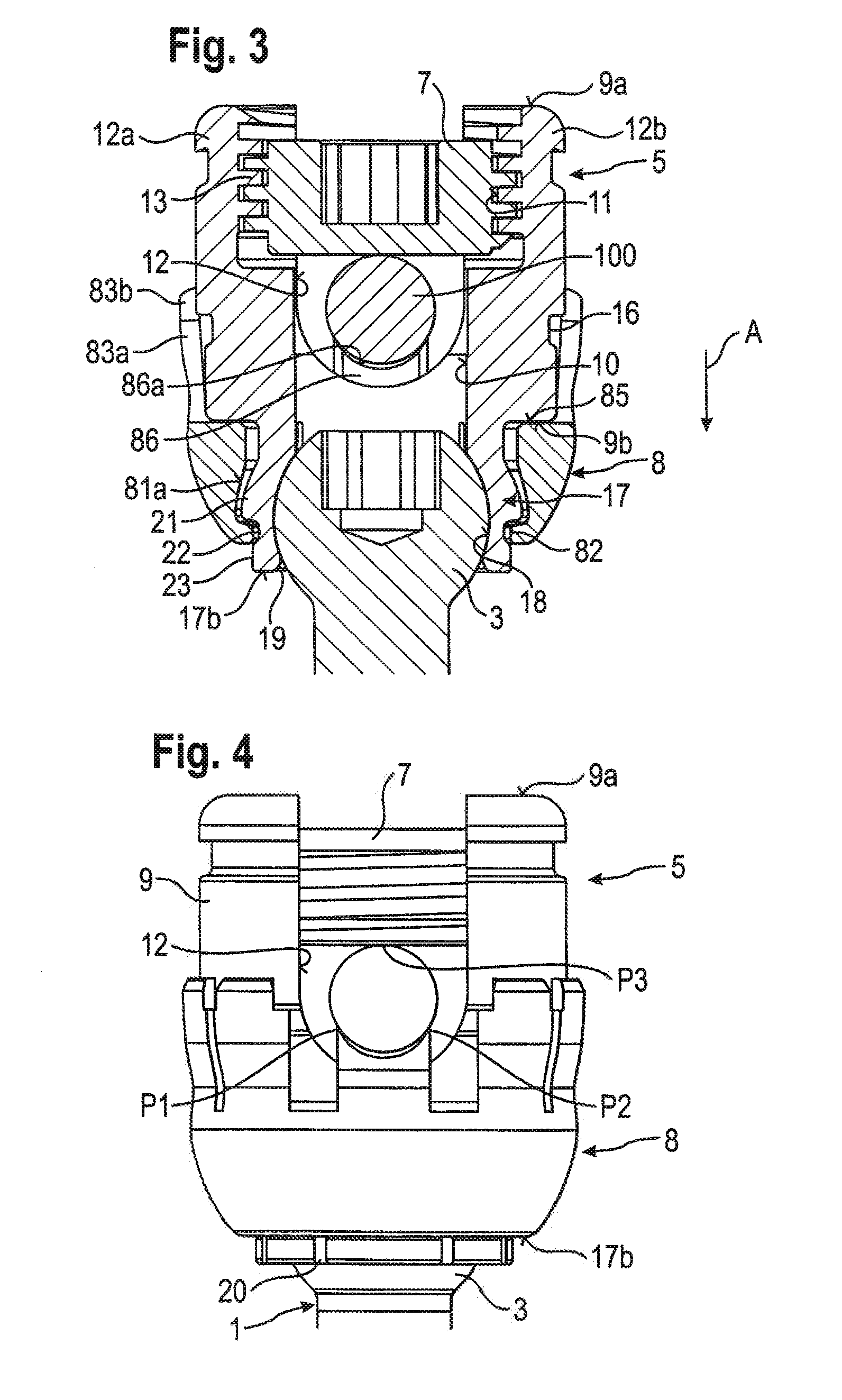
[0055]In another further modification as shown in FIGS. 15a to 15c, a V-shaped groove has concavely curved sidewalls 864a′ of the V-shape, and straight sidewalls 863a′. In the modified embodiments, an inserted rod can also rest on the free end surface 86a′ along two contact areas P1, P2.

[0056]FIGS. 14a to 14c and FIGS. 15a to 15c schematically show contacts formed by various rods 100, 101, 102 with increasing diameter. The rods in each case rest in the V-shaped groove on two cross-sectional points, or when seen three-dimensionally, along two contact areas P1, P2 in the form of line contacts. From above, the rods may be clamped by the inner screw 7. Hence, each rod can be in a stable clamping position ...


PUM


Abstract

A stabilization assembly for stabilizing a vertebra or other bone includes: at least two rods having different diameters; an anchoring element having a shaft and a head; a receiving part for interchangeably receiving any one of the rods to connect the rod to the anchoring element, the receiving part including a rod receiving portion with a channel for receiving the rod, and a head receiving portion having an open end and being flexible to allow introduction and clamping of the head; and a locking ring configured to be arranged around the head receiving portion and to clamp the head in the head receiving portion; wherein the locking ring includes a contact surface configured to contact any one of the at least two rods at at least two distinct contact areas that are spaced apart from one another in a circumferential direction of the rod.

Description

CROSS-REFERENCE TO RELATED APPLICATIONS[0001]The present application claims the benefit of U.S. Provisional Patent Application Ser. No. 61 / 426,757, filed Dec. 23, 2010, the contents of which are hereby incorporated by reference in its entirety, and claims priority to European Patent Application EP 1.0 196 866.7, filed Dec. 23, 2010, the contents of which are hereby incorporated by reference in its entirety.BACKGROUND[0002]1. Field of the Invention[0003]The invention relates to a stabilization device for stabilizing vertebrae or bones that includes a bone anchoring device and at least two stabilization rods having different diameters.[0004]2. Description of Related Art[0005]For stabilizing the spinal column, bone anchoring devices are known that include a shaft to be anchored in bone and a head to be connected to a rod. Usually, a rod connects several bone anchoring devices. Depending on the medical condition and the region of the spine that is to be stabilized, rods with different d...

Claims


Application Information

Patent Timeline
IPC IPC(8): A61B17/70A61B17/88
CPCA61B17/7037A61B17/70A61B17/86
Inventor BIEDERMANN, LUTZMATTHIS, WILFRIEDDANNECKER, BERTHOLD
Owner BIEDERMANN TECH GMBH & CO KG
Why Eureka
Try Eureka