Organic electroluminescent device

a technology of electroluminescent devices and electroluminescent devices, which is applied in the direction of thermoelectric device junction materials, semiconductor devices, electrical apparatus, etc., can solve the problems of inferior hole injection efficiency of electroluminescent devices, short lifetime, and inferior thermal stability, so as to improve light emission efficiency, reduce driving voltage, and prolong life

Inactive Publication Date: 2012-07-05
AU OPTRONICS CORP
View PDF3 Cites 9 Cited by
  • Summary
  • Abstract
  • Description
  • Claims
  • Application Information

AI Technical Summary

Benefits of technology

[0008]The disclosure provides an organic electroluminescent device which has enhanced light emitting efficiency, a lower driving voltage, and a longer lifetime.

Problems solved by technology

However, the p-type dopants currently used in the hole injection layer have disadvantages such as inferior thermal stability, being prone to crystallization, and being unsuitable for optical tooling, so that the electroluminescent device has inferior hole injection efficiency and a short lifetime.

Method used


Image

  • Organic electroluminescent device
  • Organic electroluminescent device
  • Organic electroluminescent device

Examples


experimental embodiment 1

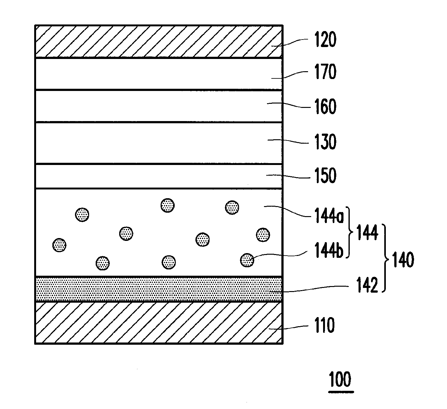
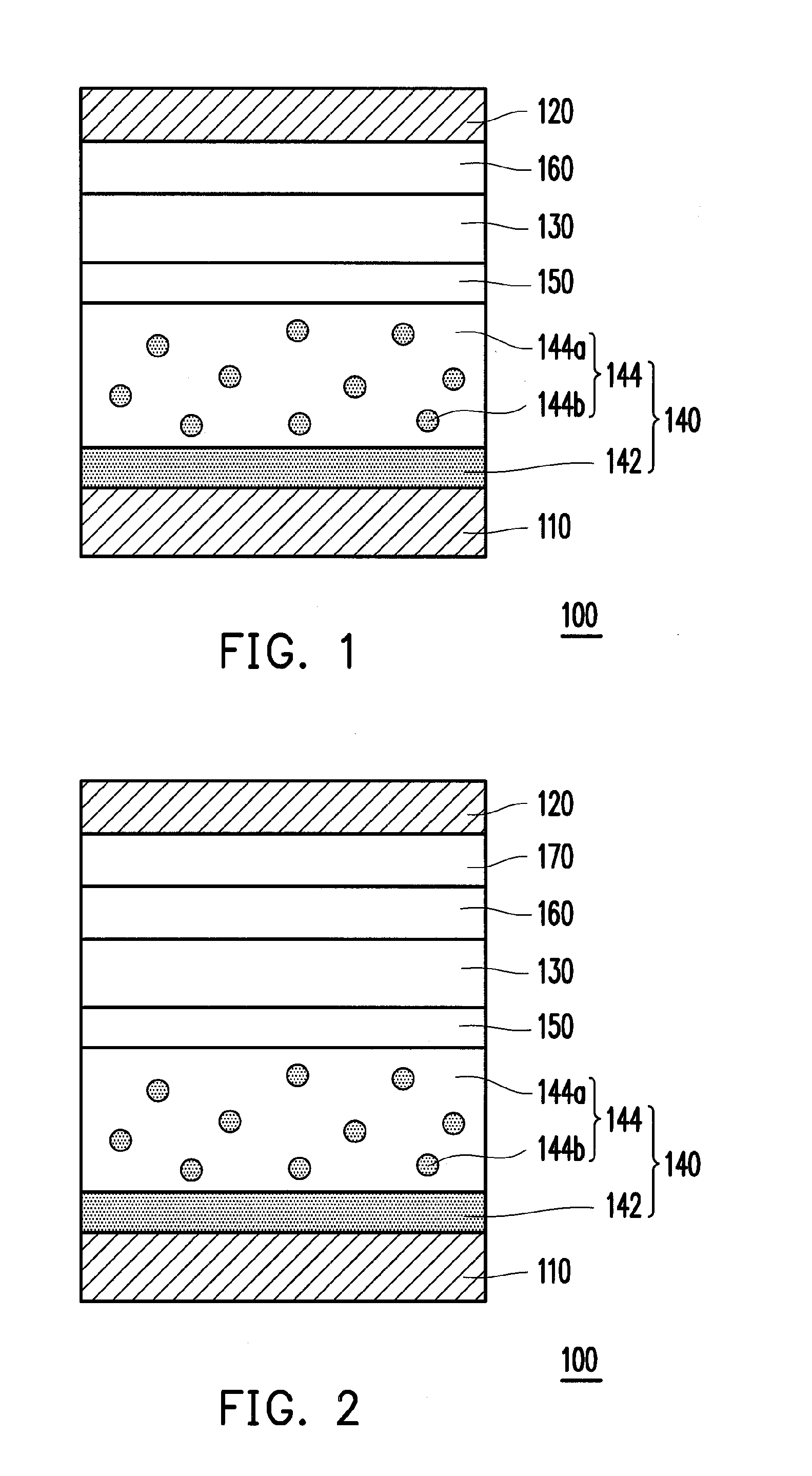
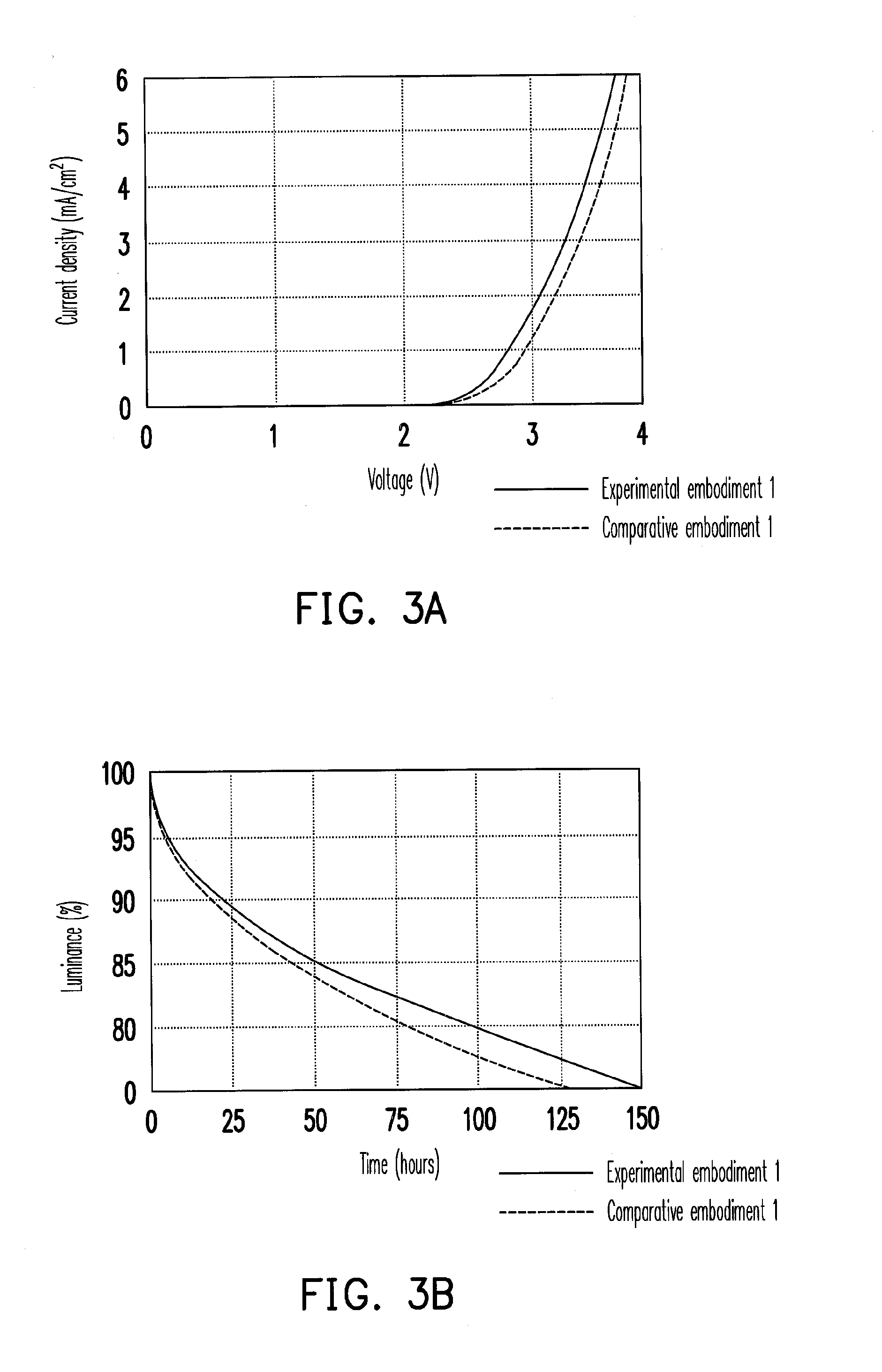
[0041]In order to verify that the organic electroluminescent device according to the above embodiments has better device characteristics and a longer lifetime, experimental embodiment 1 is compared with comparative embodiment 1. The organic electroluminescent device according to experimental embodiment 1 has a structure as shown in FIG. 1, wherein the material of the first material layer and the doping material of the second material layer are the above-mentioned HAT-CN, a thickness of the first material layer is 30 nm, and a doping concentration and a thickness of the second material layer are respectively 1.5% and 150 nm. The organic electroluminescent device according to comparative embodiment 1 has a structure as shown in FIG. 1, wherein the material of the first material layer is HAT-CN, a thickness of the first material layer is 30 nm, the doping material of the second material layer includes tetrafluoro-tetracyano-quinodimethane (F4-TCNQ), and the doping concentration and the...

experimental embodiment 2

[0043]The purpose of experimental embodiment 2 is to further verify the fact that the structure of the hole injection layer which includes the first material layer and the second material according to the disclosure enhances the light emitting efficiency of the organic electroluminescent device, compared with a convention hole injection layer formed by a single doping layer. Experimental embodiment 1 and comparative embodiment 2 are used for comparison. The organic electroluminescent device according to experimental embodiment 1 has the structure as shown in FIG. 1, wherein the material of the first material layer and the doping material of the second material layer are HAT-CN. A structure of an organic electroluminescent device according to comparative embodiment 2 is similar to the structure shown in FIG. 1, but the organic electroluminescent device according to comparative embodiment 2 has a conventional structure which includes a first electrode layer, a hole injection layer whi...


PUM


Abstract

An organic electroluminescent device including a first electrode layer, a second electrode layer, a light emitting layer and a hole injection layer is provided. The light emitting layer is disposed between the first electrode layer and the second electrode layer. The hole injection layer is disposed between the first electrode layer and the light emitting layer, wherein the hole injection layer includes a first material layer and a second material layer. The second material layer is disposed on the first material layer and includes a main material and a doping material, wherein the doping material of the second material layer and a material of the first material layer are substantially the same.

Description

CROSS-REFERENCE TO RELATED APPLICATION[0001]This application claims the priority benefit of Taiwan application serial no. 99147241, filed Dec. 31, 2010. The entirety of the above-mentioned patent application is hereby incorporated by reference herein and made a part of this specification.BACKGROUND OF THE INVENTION[0002]1. Field of the Invention[0003]The disclosure is related to an organic electroluminescent device, and in particular to an organic electroluminescent device which has greater hole injection efficiency.[0004]2. Description of Related Art[0005]Electroluminescent devices are a type of semiconductor device which is capable of converting electricity into light and has high conversion efficiency. Electroluminescent devices are commonly used as emitting devices in indicator lights, display panels, and optical reading and writing heads. Electroluminescent devices have characteristics such as having no viewing angle problems, simple manufacturing processes, low cost, high resp...

Claims


Application Information

Patent Timeline
Patent Type & Authority Applications(United States)
IPC IPC(8): H01L51/54
CPCH01L51/5088H01L51/0072H10K85/6572H10K50/17
Inventor LIN, CHANG-TINGHSU, SHIH-FENG
Owner AU OPTRONICS CORP
Why Eureka
Try Eureka