Touch surface with variable refractive index

a technology of refractive index and touch surface, which is applied in the field of touch surface with variable refractive index, can solve the problems of increasing the not easily scalable, and high cost of the above-mentioned ftir technique, so as to achieve the effect of low number of light emitters and/or detectors

Inactive Publication Date: 2012-07-05
FLATFROG LAB
View PDF1 Cites 73 Cited by
  • Summary
  • Abstract
  • Description
  • Claims
  • Application Information

AI Technical Summary

Benefits of technology

[0008]It is an object of the invention to at least partly overcome one or more of the above-identified limitations of the prior art

Problems solved by technology

The FTIR techniques described above suffer from being costly, i.a. since they require the use of a large number of detectors and often also a large number of light sources.
Furthermore, they are not readily scalable since the required numb

Method used


Image

  • Touch surface with variable refractive index
  • Touch surface with variable refractive index
  • Touch surface with variable refractive index

Examples


Embodiment Construction

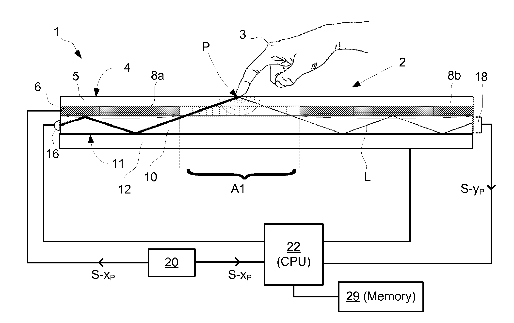
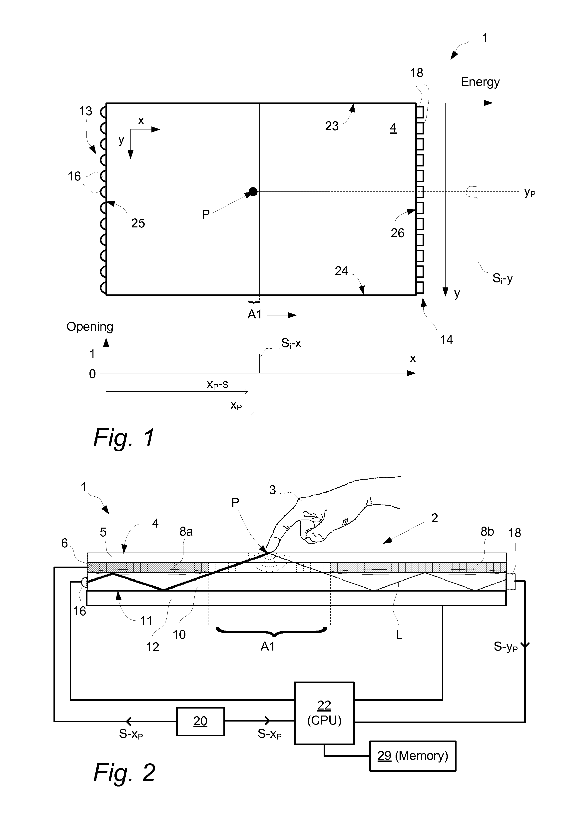
[0044]With reference to FIG. 1 and FIG. 2, an embodiment of touch-sensing apparatus 1 for determining a location P of an object 3 that touches a touch surface 4 is illustrated. The touch-sensing apparatus 1 comprises a light-transmissive panel 2 with an upper surface that defines the touch surface 4. More specifically, the panel 2 may be planar or curved and has an upper touch layer 5 defining the touch surface 4, a first layer 6 arranged underneath the touch layer 5, and a second layer 10 arranged underneath the first layer 6 and at its lower side defining an opposite surface 11 generally parallel with the touch surface 4.

[0045]In FIG. 1, a Cartesian coordinate system has been introduced, with the x-axis being parallel to a first side 23 and to a second side 24 of the panel 2 while the y-axis is parallel to a third side 25 and to a fourth side 26 of the panel 2. The exemplified panel 2 has a rectangular shape but may just as well be e.g. circular, elliptical or triangular, and anot...


PUM


Abstract

An apparatus for determining a location of at least one object on a touch surface, comprising: a light transmissive panel defining the touch surface and including a controllable reflective boundary; an illumination arrangement configured to introduce light into the panel; a control device configured to selectively control the reflective boundary such that the light may pass between a first layer and a second layer via an opening in the reflective boundary; a light detection arrangement configured to measure the light passed via the opening and impinged on the touch surface; and a processor unit configured to determine the location as a function of the measured light passed via the opening and the selective control of the reflective boundary. A method and computer readable medium is also described.

Description

CROSS-REFERENCE TO RELATED APPLICATIONS[0001]The present application claims the benefit of Swedish patent application No. 0950650-2, filed 11 Sep. 2009, and U.S. provisional application No. 61 / 272,321, filed 11 Sep. 2009, both of which are incorporated herein by reference.TECHNICAL FIELD[0002]The invention relates to techniques for detecting the location of an object on a touch surface. The touch surface may be part of a touch-sensitive panel.BACKGROUND ART[0003]To an increasing extent, touch-sensitive panels are being used for providing input data to computers, cell phones, electronic measurement and test equipment, gaming devices, etc. The panel may be provided with a graphical user interface (GUI) for a user to interact with using e.g. a pointer, stylus or one or more fingers. The GUI may be fixed or dynamic. A fixed GUI may e.g. be in the form of printed matter placed over, under or inside the panel. A dynamic GUI can be provided by a display screen integrated with, or placed un...

Claims


Application Information

Patent Timeline
IPC IPC(8): G06F3/042
CPCG06F2203/04109G06F3/0421
Inventor CHRISTIANSSON, TOMAS
Owner FLATFROG LAB
Why Eureka
Try Eureka