Reading Optical Lens Module
- Summary
- Abstract
- Description
- Claims
- Application Information
AI Technical Summary
Benefits of technology
Problems solved by technology
Method used
Image


Examples
first embodiment
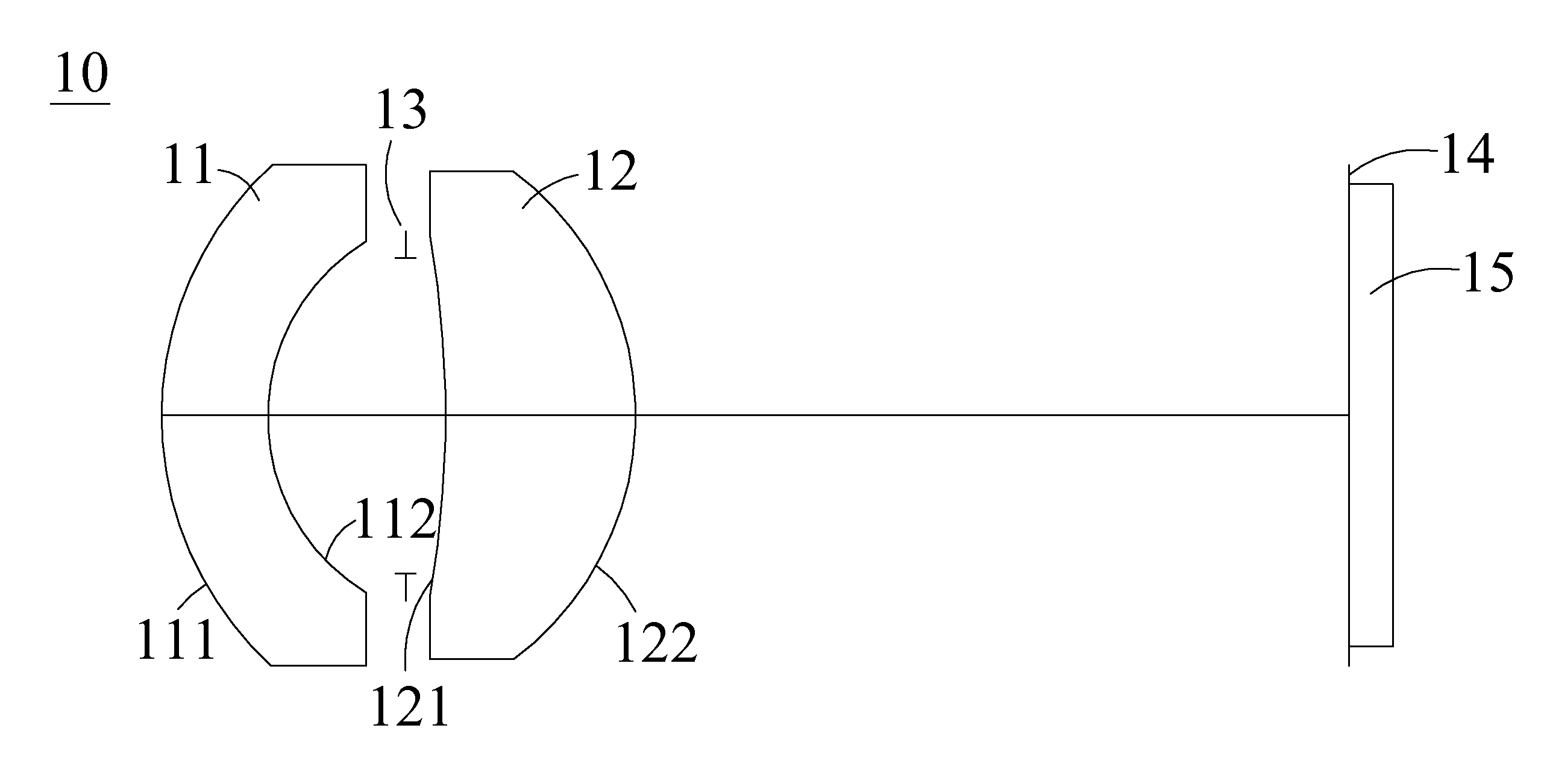
[0032]Refer to FIG. 2, a diagram depicting the first embodiment of the reading optical lens module according to the present invention is shown, whose light path diagram can be referred to FIG. 3, and the astigmatic aberration curve for the first embodiment can be referred to FIG. 4. The reading optical lens module 10 of the first embodiment comprises, arranged along the optical axis in order from the object side to the image side, a first lens 11, an aperture stop 13, a second lens 12 and an image sensor 15. Herein the first lens 11 is a meniscus lens, in which the object side optical surface 111 of the first lens is a convex surface, the image side optical surface 112 of the first lens is a concave surface, and the object side optical surface 111 and the image side optical surface 112 of the first lens are both aspherical surfaces constructed with the aspherical surface formula (8); the second lens 12 is a meniscus lens, in which the object side optical surface 121 of the second le...
second embodiment
[0038]The astigmatic aberration curve for the second embodiment of the present invention can be referred to FIG. 5, in which the reading optical lens module 10 of the second embodiment comprises, arranged along the optical axis in order from the object side to the image side, a first lens 11, an aperture stop 13, a second lens 12 and an image sensor 15. Herein the first lens 11 is a meniscus lens, in which the object side optical surface 111 of the first lens is a convex surface, the image side optical surface 112 of the first lens is a concave surface, and the object side optical surface 111 and the image side optical surface 112 of the first lens are both aspherical surfaces constructed with the aspherical surface formula (8); the second lens 12 is a meniscus lens, in which the object side optical surface 121 of the second lens is a concave surface, the image side optical surface 122 of the second lens is a convex surface, and the object side optical surface 121 and the image side...
third embodiment
[0044]The astigmatic aberration curve for the third embodiment of the present invention can be referred to FIG. 6, in which the reading optical lens module 10 of the third embodiment, along the optical axis and sequentially arranged from the object side to the image side, comprises: a first lens 11, an aperture stop 13, a second lens 12 and an image sensor 15. Herein the first lens 11 is a meniscus lens, in which the object side optical surface 111 of the first lens is a convex surface, the image side optical surface 112 of the first lens is a concave surface, and the object side optical surface 111 and the image side optical surface 112 of the first lens are both aspherical surfaces constructed with the aspherical surface formula (8); the second lens 12 is a meniscus lens, in which the object side optical surface 121 of the second lens is a concave surface, the image side optical surface 122 of the second lens is a convex surface, and the object side optical surface 121 and the ima...
PUM
 Abstract
Description
Claims
Application Information
 - R&D
- Intellectual Property
- Life Sciences
- Materials
- Tech Scout
- Unparalleled Data Quality
- Higher Quality Content
- 60% Fewer Hallucinations
Browse by: Latest US Patents, China's latest patents, Technical Efficacy Thesaurus, Application Domain, Technology Topic, Popular Technical Reports.
© 2025 PatSnap. All rights reserved.Legal|Privacy policy|Modern Slavery Act Transparency Statement|Sitemap|About US| Contact US: help@patsnap.com