Medical device guidewire with a position sensor

a technology of position sensor and medical device, applied in the field of medical device guidewire, can solve the problems of affecting the accuracy of the positioning of the guidewire, placing unwanted stress on the structure of the guidewire, etc., and achieve the effect of reducing stress and improving accuracy

Active Publication Date: 2012-07-05
ST JUDE MEDICAL INT HLDG SARL
View PDF27 Cites 47 Cited by
  • Summary
  • Abstract
  • Description
  • Claims
  • Application Information

AI Technical Summary

Benefits of technology

[0008]One advantage of the methods and apparatus described, depicted, and claimed herein relates to a reduction in the stress experienced in or by the position sensor and related wiring in a medical device when the device is su

Problems solved by technology

Such contact can place unwanted stress on the structure

Method used


Image

  • Medical device guidewire with a position sensor
  • Medical device guidewire with a position sensor
  • Medical device guidewire with a position sensor

Examples


first embodiment

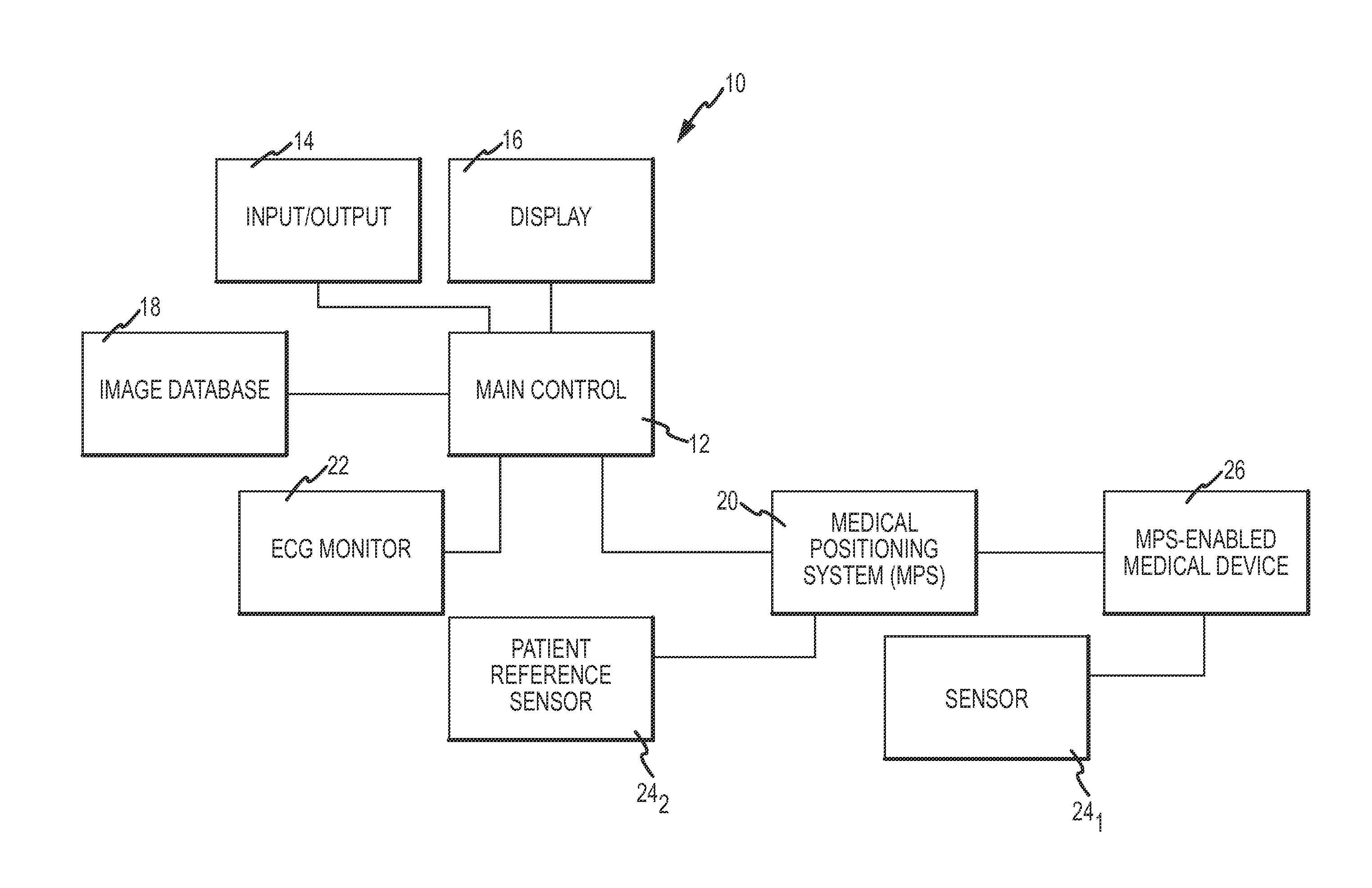
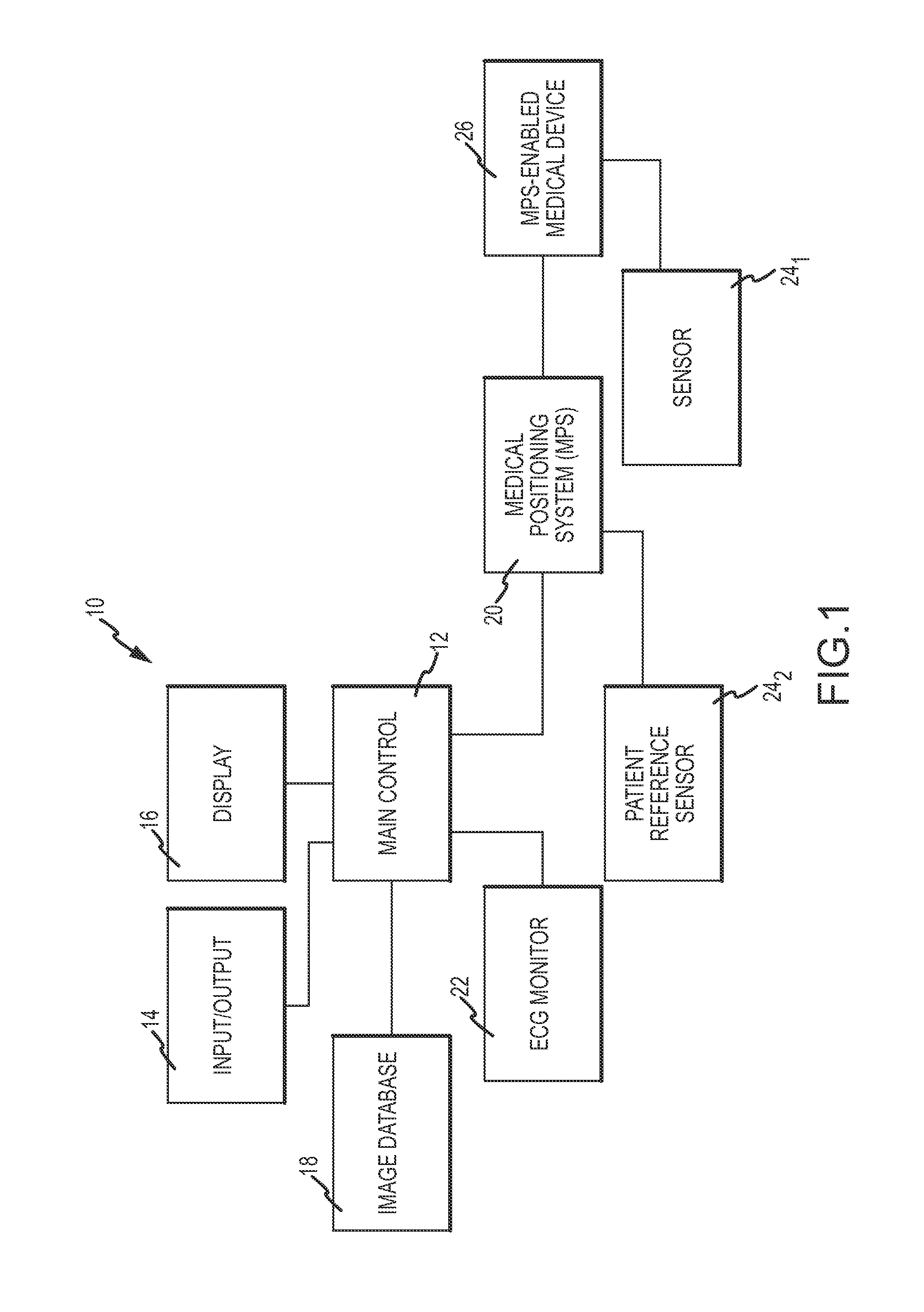
[0032]FIG. 3 is a diagrammatic view of a guidewire 36 that may be used as device 26 in system 10, with portions of a shroud broken away to more clearly show the interior components. Guidewire 36 has a distal end 38 and a proximal end 40. As used with reference to a guidewire, “distal” refers to an end that is advanced to the region of interest within a body while “proximal” refers to the opposite end that is disposed outside of the body and manipulated manually by a clinician or automatically through, for example, robotic controls.

[0033]Guidewire 36 includes a central corewire 42 and a generally thin-walled elongate shroud 48 defining an interior which contains corewire 42 and is configured in size and shape to receive a sensor 44. Sensor 44, and optionally a sheath 46 surrounding sensor 44, are disposed within the interior. In the illustrated embodiment, corewire 42 extends through sensor 44. A plug 50 is provided at the extreme distal end of guidewire 36 for structural support and...

embodiment 74

[0048]FIG. 9 is a cross-sectional view of a second guidewire embodiment 74. The distal end of guidewire 74 is substantially the same as distal end 38 of guidewire 36, except guidewire 74 lacks a shroud. Instead, a tubular spring 76 extends to and may be coupled to plug 50. Corewire 42, sensor 44, sheath 46 (if provided), and connection node 56 all may be potted together inside spring 76. Spring 76 may comprise radiopaque material, such as platinum, to increase fluoroscopic visibility.

embodiment 78

[0049]FIG. 10 is a cross-sectional view of a third guidewire embodiment 78. The interior of the distal end of guidewire 78 is substantially the same as distal end 38 of guidewire 36. However, guidewire 78 lacks a shroud and in lieu thereof its distal end is covered by a coating 80. Coating 80 may comprise a polymer layer extending proximally from plug 50, covering sensor 44, wiring 54, and spring 52. Coating 80 completely circumferentially surrounds sensor 44 and connection node 56, just like shroud 48 (FIG. 3) and spring 76 (FIG. 9). Coating 80 advantageously seals the distal end of guidewire 80, rendering it watertight, and may be hydrophilic or hydrophobic. Coating 80 also creates a smooth, continuous surface which is advantageous in some applications, such as delivering pace-makers and other implantable device leads.

[0050]FIG. 11 is a schematic and block diagram of one exemplary embodiment of MPS 20, designated as an MPS 108, as also seen by reference to U.S. Pat. No. 7,386,339,...


PUM


Abstract

A guidewire for a medical device is disclosed. In one embodiment, the guidewire includes a corewire having a proximal end portion and a distal end portion, an elongate shroud disposed about the corewire, the shroud having a distal end, and a plug coupled with the distal end portion of the corewire and the distal end of the shroud, the plug having a distal, non-traumatic tip portion, an interior between the corewire and the shroud being configured to receive a sensor.

Description

BACKGROUND OF THE INVENTION[0001]a. Field of the Invention[0002]The instant invention relates generally to a medical device guidewire, and more specifically to a medical device guidewire with a position sensor.[0003]b. Background Art[0004]Various diagnostic and therapeutic procedures in or on the body of a patient, such as in the circulatory system, the gastrointestinal tract, the brain vessels, the bronchial tree or the like may be performed or facilitated by inserting a catheter into a body lumen and thereafter navigating the diagnostic or therapeutic catheter to the target anatomical site. To facilitate navigation of the catheter, a guidewire is often used. The guidewire typically has a reduced diameter relative to the catheter; the reduced diameter aids a physician in inserting and navigating the guidewire to the anatomical site. The catheter is then passed over the guidewire and guided to the target site.[0005]One method for maneuvering a guidewire involves the use of fluorosco...

Claims


Application Information

Patent Timeline
IPC IPC(8): A61M25/09
CPCA61B5/062A61M2025/09166A61M25/09041A61M2025/0166A61M2025/09075A61M2025/09083A61M2025/09175A61M2025/09183A61B2019/5251A61B5/6851A61B19/54A61B2019/5466A61M2025/09091A61M2025/09108A61M25/09A61B2034/2051A61B90/39A61B2090/3966
Inventor MELLER, NIMRODSELA, RANSETER, DANSOBE, LIOR
Owner ST JUDE MEDICAL INT HLDG SARL
Why Eureka
Try Eureka