Cooling apparatus and cooling method for hot rolling

Active Publication Date: 2012-07-12
NIPPON STEEL CORP
View PDF1 Cites 4 Cited by
  • Summary
  • Abstract
  • Description
  • Claims
  • Application Information

AI Technical Summary

Benefits of technology

[0024]According to the present invention, the shape of the leading end and the trailing end of the steel sheet can be improved, and vibration of the steel she

Problems solved by technology

Conventionally, for the reason described above, because temperature differences occur even when attempting to perform cooling uniformly across the surface of the steel sheet 103, manufacturing a steel sheet 103 h

Method used


Image

  • Cooling apparatus and cooling method for hot rolling
  • Cooling apparatus and cooling method for hot rolling
  • Cooling apparatus and cooling method for hot rolling

Examples


embodiment 1

[0034]A steel material discharged from a furnace, after being rolled to a thickness of 40 mm or thereabouts by a roughing mill (omitted in the figures above), is subjected to continuous rolling in a finishing mill 2 described later, to a thickness of 1 mm to 4 mm or thereabouts.

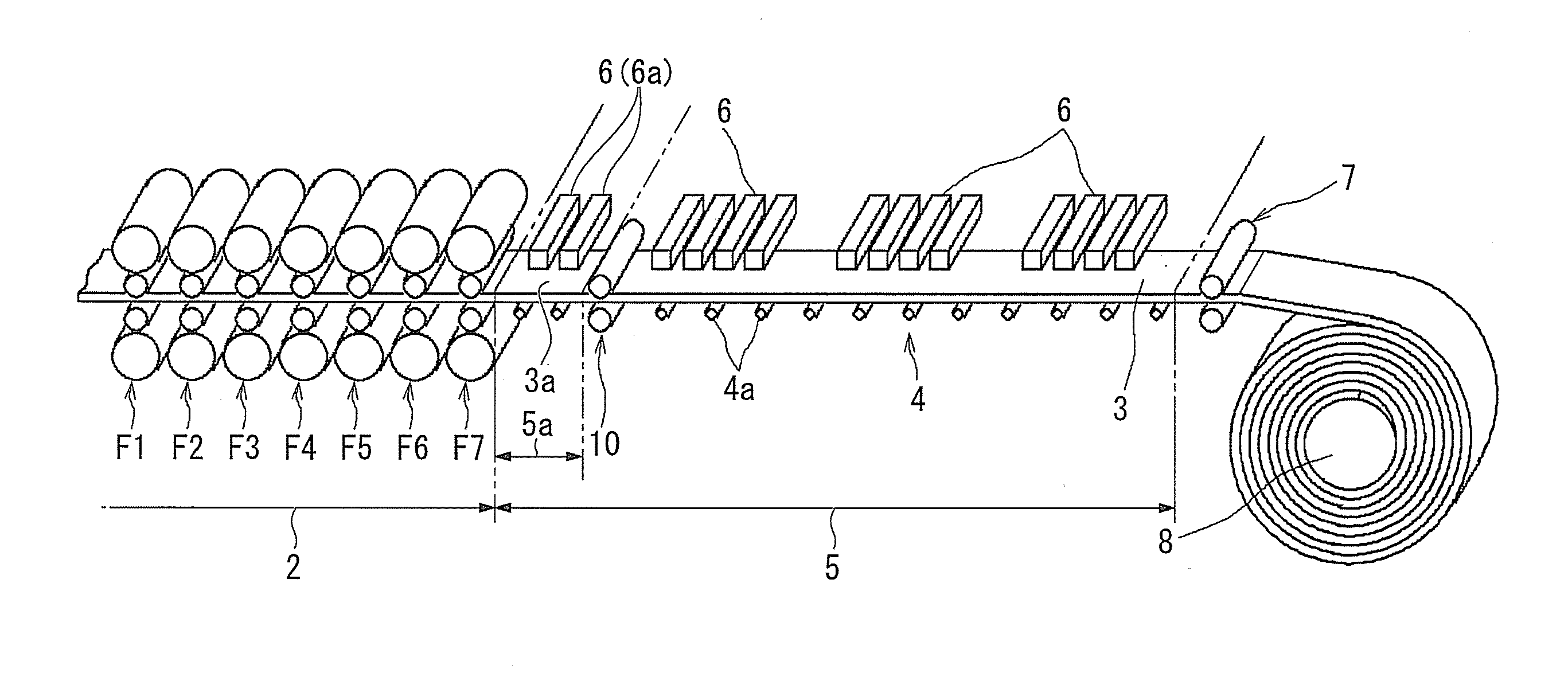
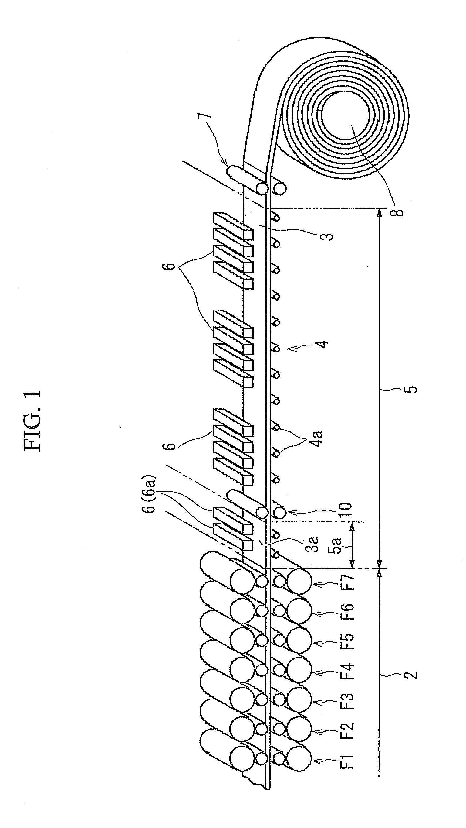
[0035]FIG. 1 is a perspective view of a hot rolling mill having a cooling apparatus 5 for hot rolling according to the present embodiment (hereafter abbreviated to a cooling apparatus 5), showing an overview of the apparatus configuration from the finishing mill 2 onward. The finishing mill 2 is provided with a plurality (for example, 7 in the illustrated example) of stands F1 to F7, and performs hot rolling so as to obtain a steel sheet 3 having a desired sheet thickness and sheet width at the point when the steel material has passed through the final stand F7. The surface temperature of the steel sheet 3 immediately after passing through the final stand F7 of the finishing mill 2 is within a range from 840°...

embodiment 2

[0062]FIG. 5 shows a second embodiment of the present invention. In the following description, only the points of difference from the first embodiment are described, and any duplicate description is omitted.

[0063]In the present embodiment, inside the cooling apparatus 5, first intermediate pinch rolls 11 (second pinch rolls) and second intermediate pinch rolls 12 (third pinch rolls) are provided. Furthermore, the first intermediate pinch rolls 11 are installed at a position where the surface temperature of the steel sheet 3 is 650° C. to 550° C., and the second intermediate pinch rolls 12 are installed at a position where the surface temperature of the steel sheet 3 is 450° C. to 350° C. The first intermediate pinch rolls 11 and the second intermediate pinch rolls 12 each have an upper and lower pair of rolls which, while applying tension of 3.9 MPa or greater to a section 3b of the steel sheet 3 between the position where the first intermediate pinch rolls 11 are installed and the ...


PUM

PropertyMeasurementUnit
Temperatureaaaaaaaaaa

Abstract

A cooling apparatus for hot rolling is installed on a downstream side of a finishing mill of a continuous hot rolling mill, and cools a steel sheet rolled by the finishing mill while being conveyed. The cooling apparatus includes first pinch rolls which, during an interval when the steel sheet fed out from a final stand of the finishing mill moves from a position of the final stand to a position where a surface temperature of the steel sheet reaches 850° C. or less, pinch the steel sheet while applying tension of 3.9 MPa or greater.

Description

TECHNICAL FIELD[0001]The present invention relates to a cooling apparatus and a cooling method for cooling a steel sheet on a run-out table after finish rolling is performed during continuous hot rolling of the steel sheet.BACKGROUND ART[0002]A steel material discharged from a furnace is sent via a roughing mill to a finishing mill. FIG. 6 is a perspective view showing an example of a layout of a hot rolling mill which performs a hot rolling process following on from a finishing mill 102. As shown in this FIG. 6, the steel material undergoes continuous rolling in a finishing mill 102 provided with a plurality of stands F1a to F7a. Then, a steel sheet 103 hot rolled to a desired thickness via the final stand F7a, is conveyed by a run-out table 104 provided with a plurality of conveying rollers 104a. [0003]The run-out table 104 is installed inside a cooling apparatus 105 located on the downstream side of the finishing mill 102. Moreover, from a plurality of cooling units 106 provided ...

Claims


Application Information

Patent Timeline
IPC IPC(8): B21B45/02B21B39/08
CPCB21B45/0218B21B2265/02B21B2261/20B21B39/006B21B39/08B21B45/02
Inventor SERIZAWA, YOSHIHIROOGAWA, SHIGERUNAKAMURA, YOJIAKASHI, TOORUHISHINUMA, NORIYUKIKISHIMOTO, TETSUO
Owner NIPPON STEEL CORP
Why Eureka
Try Eureka