Optical apparatus, method, and applications

a technology of optical apparatus which is applied in the field of optical apparatus, can solve the problems of reducing free spectral range, narrow range, and limited resolution of etched diffraction grating and arrayed waveguide grating (awg), and achieves a high resolution effect and significant effective resolution

a technology of optical apparatus which is applied in the field of optical apparatus, can solve the problems of reducing free spectral range, narrow range, and limited resolution of etched diffraction grating and arrayed waveguide grating (awg), and achieves a high resolution effect and significant effective resolution

US20120177060A1Active Publication Date: 2012-07-12CORNELL UNIVERSITY

Image

  • Optical apparatus, method, and applications
  • Optical apparatus, method, and applications
  • Optical apparatus, method, and applications

Examples


Embodiment Construction

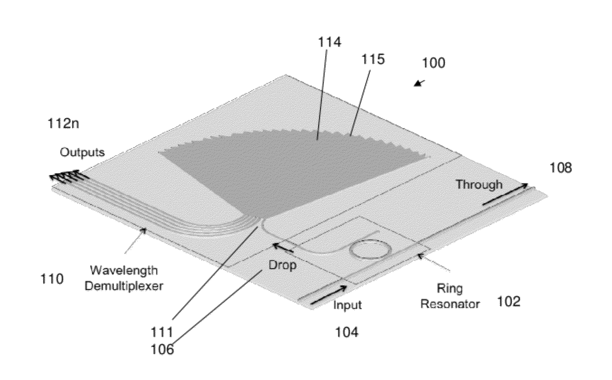
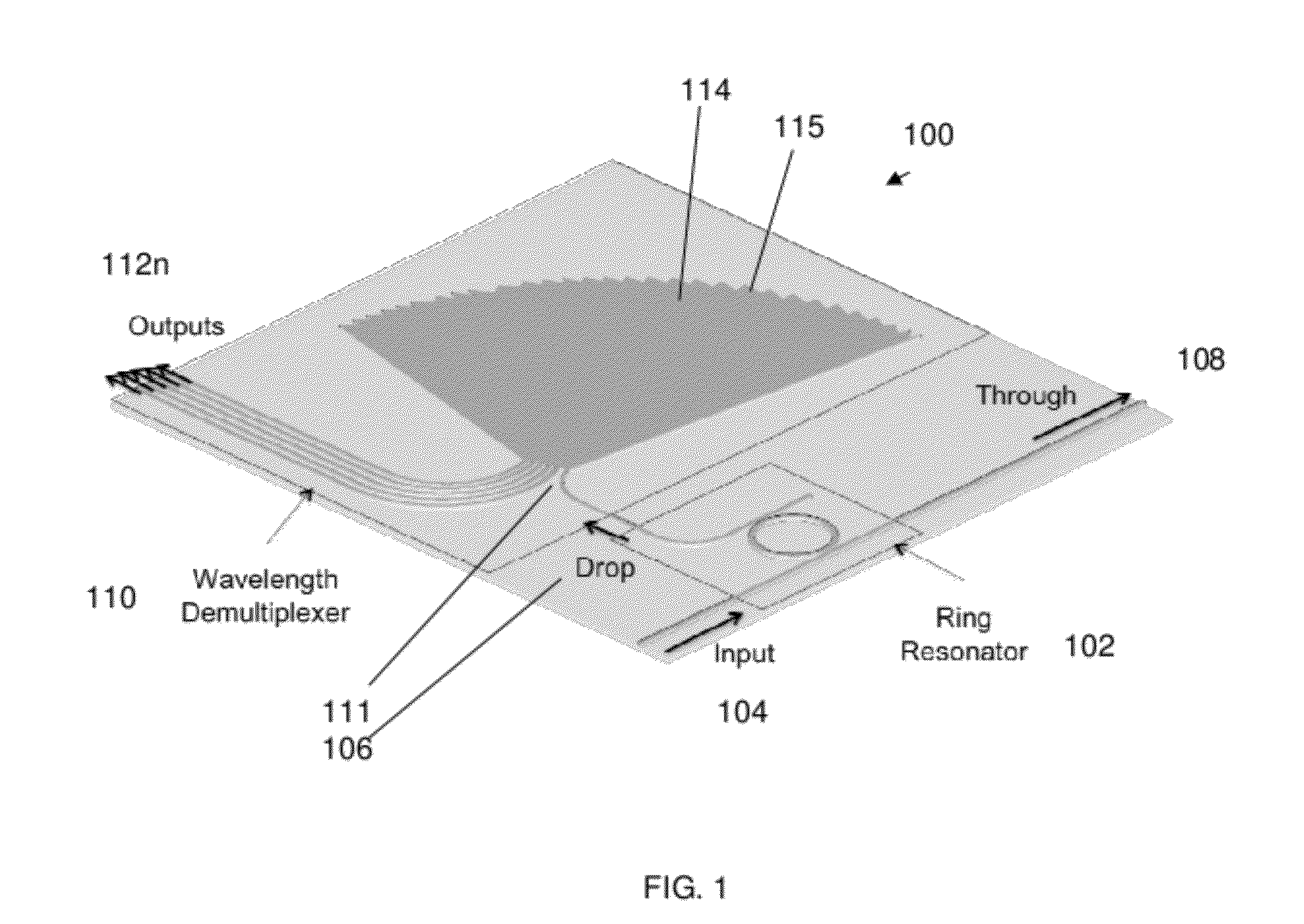
[0038]FIG. 1 illustrates an exemplary high resolution, wide spectral range spectrometer apparatus 100. The apparatus includes an optical resonant cavity 102 in the form of a ring resonator including an input 104, an output 106 in the form of a drop-port, and a through port 108. The apparatus 100 further includes a wavelength demultiplexer 110 in the form of a diffraction grating 114 having an input 111 that is coupled to the drop-port 106 of the ring resonator, and a plurality of outputs 112n (here, e.g., n=5).

[0039]Multiple resonator input wavelengths that are matched to the ring cavity resonances and which are separated by a free spectral range (FSR) can be transmitted from the input 104 to the output 106. The plurality of demultiplexer outputs 112n have a channel spacing that is closely matched to the FSR of the optical resonant cavity. The wavelength demultiplexer 110 is in the form of a diffraction grating 114.

[0040]In operation, light is launched into the input 104 of the ring...


PUM


Abstract

A high resolution, wide spectral range, optical apparatus that includes an optical resonator cavity and a wavelength demultiplexer, arrangeable in multiple configurations. A method for increasing the resolution of a wavelength demultiplexer involves inputting light into an optical resonant cavity; inputting a plurality of different resonant output wavelengths to a wavelength demultiplexer; and routing each different resonant wavelength to a different output waveguide of the demultiplexer to generate a demultiplexer output spectrum. The method further involves performing either a time serialization or a space serialization procedure to increase the channel density and fully cover the spectrum of interest.

Description

CROSS-REFERENCE TO RELATED APPLICATIONS[0001]The instant application claims priority to U.S. Provisional Application No. 61 / 377,222 filed on Aug. 26, 2010, the subject matter of which is incorporated herein by reference in its entirety.GOVERNMENT FUNDING[0002]This invention was made with government support under Award No. W911NF-07-1-0668 awarded by the Army Research Office. The government has certain rights in the invention.BACKGROUND OF THE INVENTION[0003]1. Field of the Invention[0004]Embodiments of invention generally relate to optical apparatus, methods, and applications thereof and, more particularly to optical apparatus including an optical resonant cavity combined with a wavelength demultiplexer, for e.g. but not limited to, resolution-enhanced spectrometers, light compositors, and wavelength-division multiplexing devices, and associated methods and applications.[0005]2. Description of the Related Art[0006]Several difficulties arise in the design of high resolution, wide ran...

Claims


Application Information

Patent Timeline
12 Jul 2012
Publication
US20120177060A1
IPC
H04J14/02; G02B6/34; G02B6/42
CPC
G02B6/12007; G02B6/29307; H04J14/0201; G02B6/2931; H04J14/02; G02B6/29308
Inventors
LIPSON, MICHAL; KYOTOKU, BERNADO