Method for machining a dental prosthesis

a technology for dental prostheses and machining methods, which is applied in the field of manufacturing dental prostheses, can solve the problems of reducing affecting the quality of dental prostheses, so as to reduce the likelihood of forming tool failur

Inactive Publication Date: 2012-07-12
JUNG YUNOH +1
View PDF0 Cites 22 Cited by
  • Summary
  • Abstract
  • Description
  • Claims
  • Application Information

AI Technical Summary

Benefits of technology

[0007]It has been recognized that it would be advantageous to develop a method for machining a dental prosthesis that reduces the likelihood of forming tool failure.

Problems solved by technology

The drawback is that a small tool is not as strong as a larger tool of the same quality.
Harder materials are more difficult to machine than materials of lesser hardness.
The smaller forming tools typically used to machine dental prostheses may be prone to failure due to the increased stress of machining harder materials and this may be particularly troublesome when machining a bottom surface of a dental prosthesis.

Method used


Image

  • Method for machining a dental prosthesis
  • Method for machining a dental prosthesis
  • Method for machining a dental prosthesis

Examples


Embodiment Construction

)

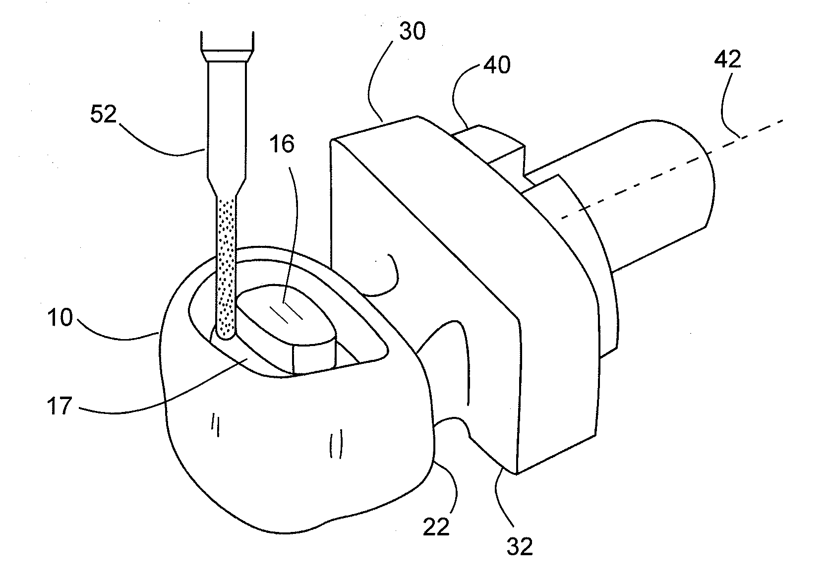
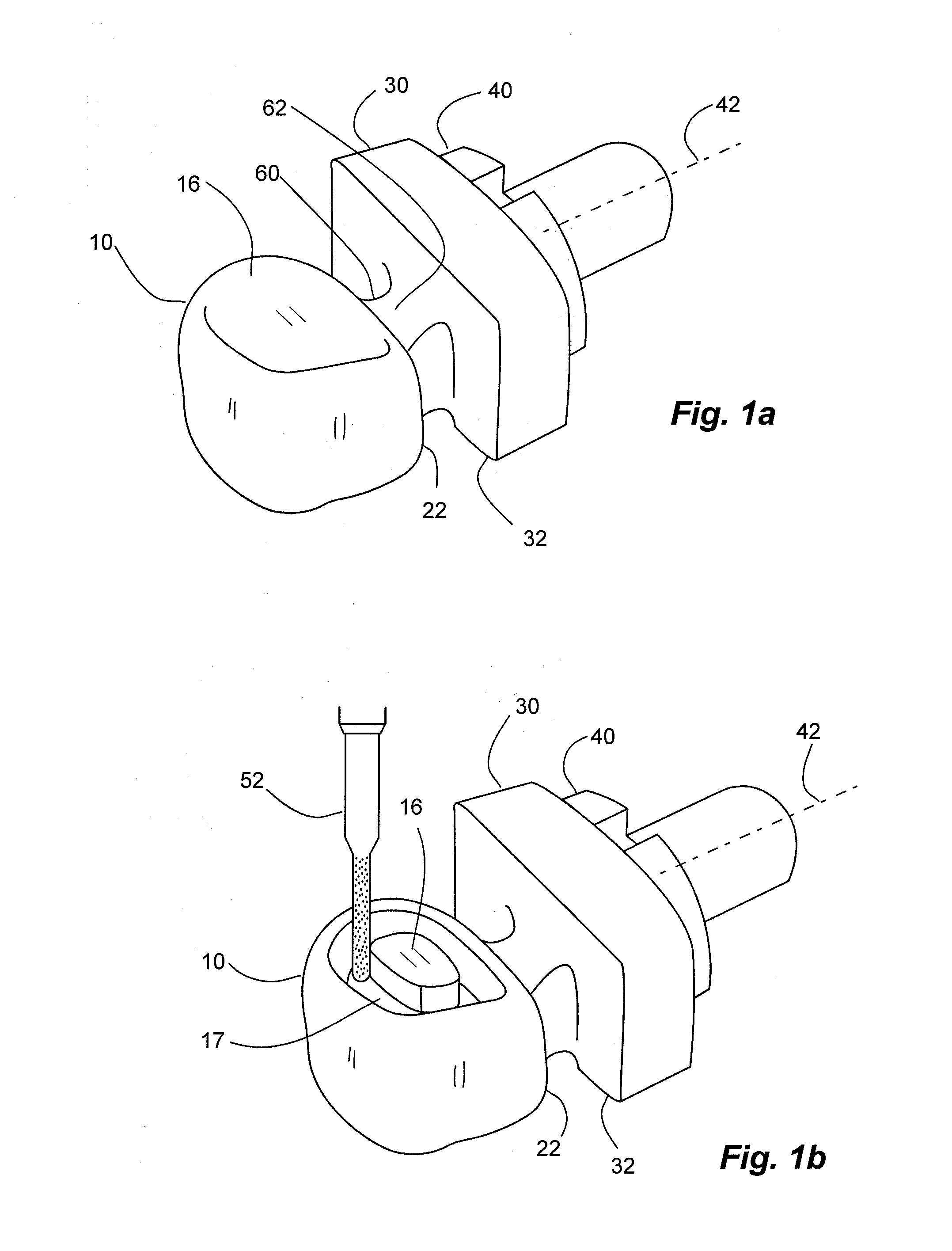
[0027]The invention provides a method for cutting a dental prosthesis from a workpiece by machining a bottom of the dental prosthesis first, and then subsequently machining a top of the dental prosthesis. In addition, the method provides for first machining a bottom perimeter of the dental prosthesis, and then subsequently machining a bottom cavity of the dental prosthesis. A sweep path (e.g. back and forth from a distal to proximal end) is used to machine the bottom perimeter, and a spiral path (e.g. around from outer to inner and upper to lower) is used to machine the bottom cavity.

[0028]Illustrated in FIGS. 1a and 1b is a dental prosthesis 10 during manufacture in an example embodiment in accordance with the invention. In this embodiment, a workpiece 30 may be attached to a fixture 40. A connector 60 can be between a proximal end 22 of the dental prosthesis 10 and a proximal end 32 of the workpiece 30. Also illustrated is that the dental prosthesis 10 may be formed by a forming ...


PUM

PropertyMeasurementUnit
relative rotationaaaaaaaaaa
perimeteraaaaaaaaaa
strengthaaaaaaaaaa

Abstract

A method for machining a dental prosthesis that reduces the likelihood of forming tool failure includes machining a workpiece to form a bottom surface without machining a bottom cavity of the dental prosthesis, then machining the bottom cavity and machining the top.

Description

RELATED APPLICATION(S)[0001]This is related to application Ser. No. 12 / 963,856, filed Dec. 9, 2010, which is herein incorporated by reference in its entirety.BACKGROUND[0002]1. Field of the Invention[0003]The present invention relates generally to manufacturing a dental prosthesis. More particularly, the present invention relates to machining a dental prosthesis.[0004]2. Related Art[0005]Various different methods have been developed for manufacturing dental prostheses. One type of manufacturing process used to manufacture dental prostheses is machining. A machining process may form a part by removing material. A forming tool may be used to remove material. Typical forming tools may remove material by cutting or abrading. For example, an end mill is a typical “cutter” and a grinder is typical of an abrading tool. A machine tool rotates the forming tool, typically at a high speed, so that the forming tool can remove material from a workpiece. A typical workpiece may begin as a solid b...

Claims


Application Information

Patent Timeline
Patent Type & Authority Applications(United States)
IPC IPC(8): B23B35/00B32B3/06B23B51/00
CPCB23C3/00A61C13/0004A61C13/0022Y10T428/24008Y10T408/83Y10T408/03B23C2226/18
Inventor JUNG, YUNOHJUNG, DANIEL YONIL
Owner JUNG YUNOH
Why Eureka
Try Eureka