
Propeller Connecting Piece for Electric Model Airplane

a technology for electric models and connecting parts, applied in the field of electric model airplanes, can solve the problems of motor main shaft bent to be out of work, model airplane damage, and prone to impact on the propeller during flying, so as to avoid damage to the motor-powered model airplane and its power system

Inactive Publication Date: 2012-07-12
DDPAI TECH CO LTD
View PDF13 Cites 21 Cited by
  • Summary
  • Abstract
  • Description
  • Claims
  • Application Information

AI Technical Summary

Benefits of technology

[0006]The technical problem to be solved by the present invention is to provide a propeller connector of electric model airplane, which can, on the premise of ensuring stable and firm connection between an electric power output shaft and a propeller in the model airplane to normally transfer electric power to the propeller, separate the propeller from the electric power output shaft in time in the case of accidental impact so as to put the propeller under effective protection.
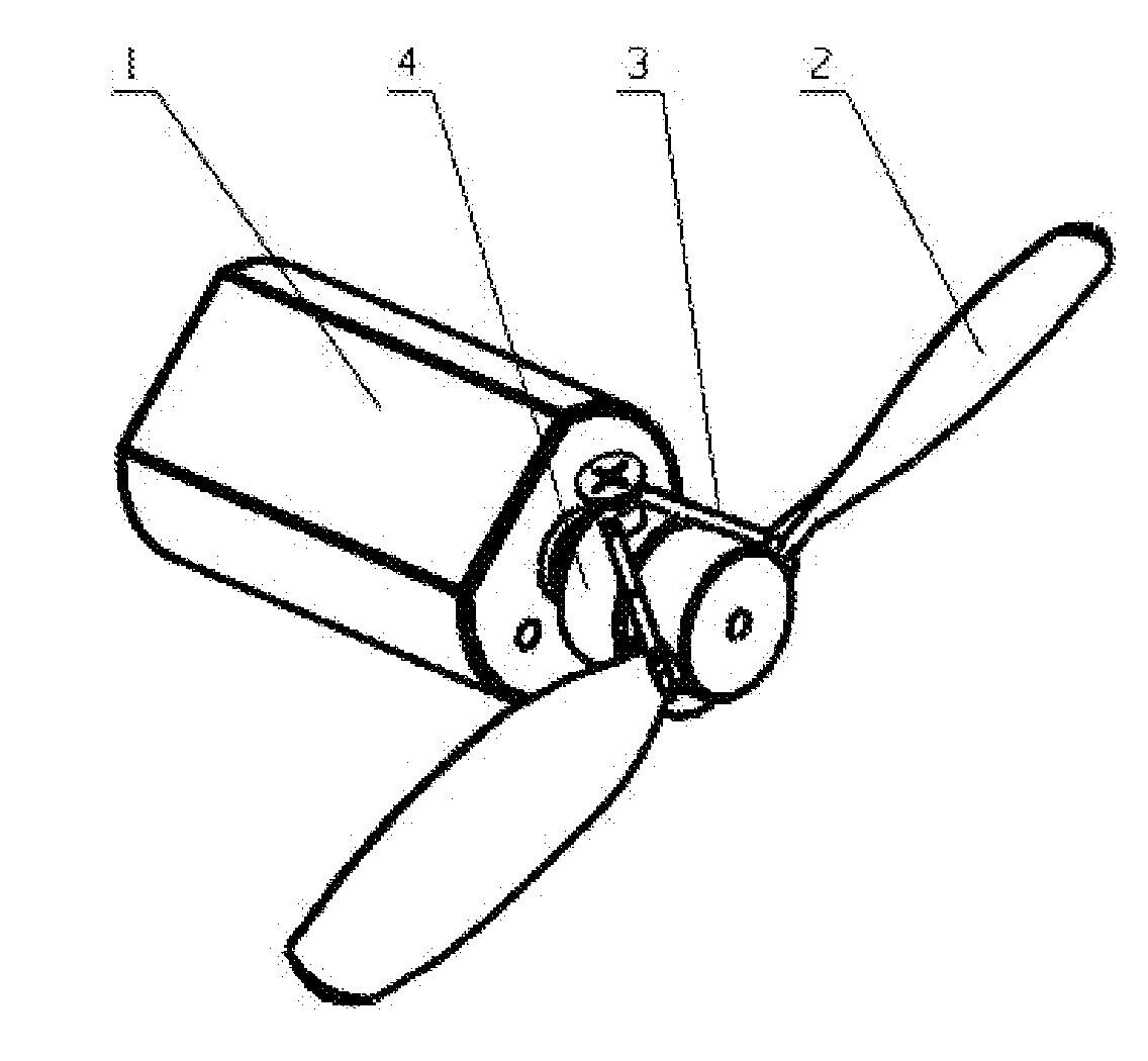
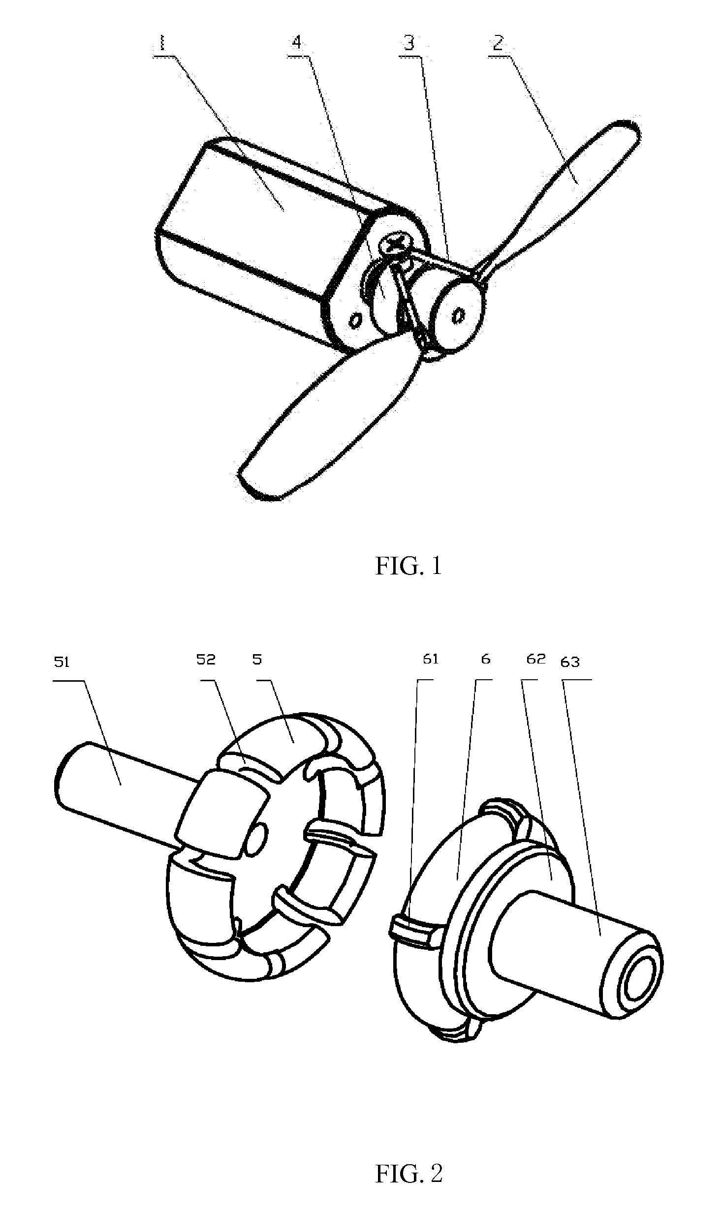
[0007]Thus, the present invention provides a propeller connector of electric model airplane, which is used for connecting an electric-power output shaft with a propeller in an electric model airplane with the propeller, the propeller connector comprises two connectors, wherein one of the connectors is connected with the electric-power output shaft of the model airplane, and the other connector is connected with the propeller of the model airplane, one of the two connectors is an elastic component provided with an opening slot, and the two connectors are coaxially connected and can rotate together, but can be conveniently separated from each other when impacted by external force;
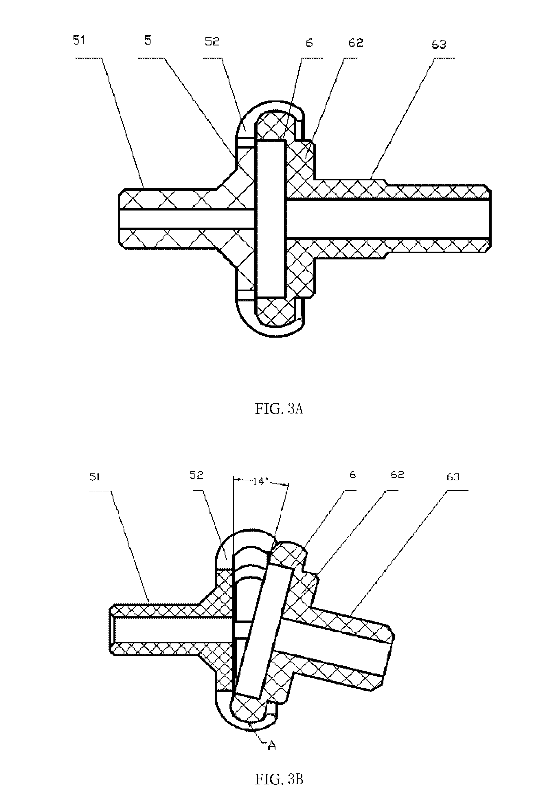
[0017]Since the propeller connector of the model airplane provided by the present invention is used for connecting the electric power output shaft (including motor shaft and final stage driven gear shaft of motor-powered reducing system) with the propeller, the propeller connector is divided into two separable connectors, with one being connected with the propeller and the other being connected with the electric power output shaft. Embedded locking between the two connectors is realized by means of elastic deformation of the connector material so as to transfer motor power to the propeller, and when the propeller is impacted, one of the connectors is pried owing to moment to pry the other connector immediately, so the loosening of the deformed connector leads to the release of the other embedded connector. Therefore, on the premise of keeping the propeller and the electric power output shaft rotating together, the damage to the motor-powered model airplane and its power system can be avoided when the propeller is impacted, thereby making an effective breakthrough on the technical bottleneck of electric model airplane with front-mounted power.

Problems solved by technology

Model airplanes, especially the small model airplanes powered by front-mounted motor, mostly fly on a small simple field, and typically, there is no flat runway for the small model airplanes to take off and land, and the propeller during flying is quite liable to be impacted by plenty of obstacles.
In the prior art, what is generally adopted is the manner that the propeller is directly fixedly connected with the motor power output shaft (including motor main shaft or power output shaft of driven gear of motor-powered reducing gear train), therefore, during flying, especially in the process of takeoff and landing of the model airplane, once the propeller is impacted by an obstacle, in milder case, the propeller is broken, and in more serious case, the motor main shaft is bent to be out of work, and even the model airplane will be damaged.
Therefore, two technical requirements in this method, i.e. transferring the rotational torque of motor and protecting the propeller from being impacted to further avoid damage, are contradictory in this simple technical proposal, so this technical measure is unsatisfactory in propeller protecting effect in practice.
Owing to the above problem, the development of front-mounted motor power model is substantially restricted, especially in the aspect of small-sized airplane.

Method used


Image

  • Propeller Connecting Piece for Electric Model Airplane
  • Propeller Connecting Piece for Electric Model Airplane
  • Propeller Connecting Piece for Electric Model Airplane

Examples


Embodiment Construction

[0036]Further detailed description is made below to the embodiments of the present invention with reference to the drawings.

[0037]The connector having the function of protecting the propeller of model airplane provided by the present invention is used for connecting the electric power output shaft (including motor shaft and final stage driven gear shaft of motor-powered reducing system) with the propeller, the propeller connector comprises two separable connectors, with one being connected with the propeller and the other being connected with the electric power output shaft. The basic working principle of the connector is as follows: embedded locking between the two connectors is realized by means of elastic deformation of the connector material so as to transfer motor power to the propeller, and when the propeller is impacted, one of the connectors is pried owing to moment to pry the other connector immediately, so the loosening of the deformed connector leads to the release of the...


PUM


Abstract

A propeller connecting piece for electric model airplane, for connecting an electric-power output shaft with a propeller in an electric model airplane with the propeller, characterized in that the propeller connector comprises two connectors, wherein one of the connectors is connected with the electric-power output shaft of the model airplane, and the other connector is connected with the propeller of the model airplane, one of the two connectors is an elastic component provided with an opening slot, and the two connectors are coaxially connected and can rotate together, but can be conveniently separated from each other when impacted by external force, so as to put the propeller under effective protection.

Description

TECHNICAL FIELD[0001]The present invention relates to the technical field of model airplane, especially to the technical field of an electric model airplane powered by front-mounted motor.BACKGROUND ART[0002]Model airplanes, especially the small model airplanes powered by front-mounted motor, mostly fly on a small simple field, and typically, there is no flat runway for the small model airplanes to take off and land, and the propeller during flying is quite liable to be impacted by plenty of obstacles. In the prior art, what is generally adopted is the manner that the propeller is directly fixedly connected with the motor power output shaft (including motor main shaft or power output shaft of driven gear of motor-powered reducing gear train), therefore, during flying, especially in the process of takeoff and landing of the model airplane, once the propeller is impacted by an obstacle, in milder case, the propeller is broken, and in more serious case, the motor main shaft is bent to ...

Claims


Application Information

Patent Timeline
Patent Type & Authority Applications(United States)
IPC IPC(8): F01D5/30
CPCB64C11/04A63H27/02
Inventor HUANG, GUOCHUANWU, YUCHEN
Owner DDPAI TECH CO LTD
Learn More