
Device, method, and system for quantitatively measuring a specimen using a camera

a technology of quantitative measurement and camera, applied in the field of quantitative measurement of specimens, can solve the problems of difficult miniaturization of analyzers, increased analysis time, and increased cost, and achieve the effect of miniaturizing the devi

Inactive Publication Date: 2012-07-12
OSANG HEALTHCARE CO LTD
View PDF7 Cites 17 Cited by
  • Summary
  • Abstract
  • Description
  • Claims
  • Application Information

AI Technical Summary

Benefits of technology

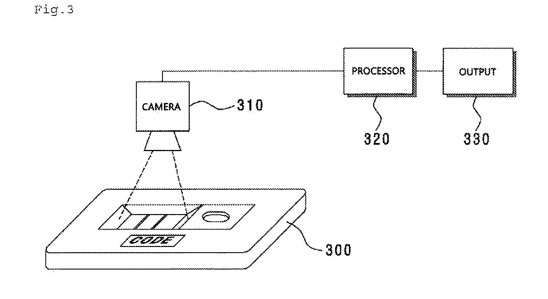
[0032]As described above, the device and method for quantitatively measuring an analyte by using a camera according to the present invention can recognize an analyte reaction result and code information by using one camera, thereby analyzing a sample quickly and miniaturizing the device because there is no need to include a code recognition device separately.
[0033]Furthermore, the device and method for quantitatively measuring an analyte by using a camera according to the present invention can recognize an analyte reaction result and code information by using one camera, thereby analyzing the recognized information with software.

Problems solved by technology

However, using typical bar code readers or RFID units needs additional equipment for reading codes separately from photographing a reaction result of a diagnostic kit, and thus the miniaturizing of an analyzer is difficult and also additional cost arises.
Moreover, since additional operations of reading codes are needed, it takes more time for analysis and also operation processes are more complicated.

Method used


Image

  • Device, method, and system for quantitatively measuring a specimen using a camera
  • Device, method, and system for quantitatively measuring a specimen using a camera
  • Device, method, and system for quantitatively measuring a specimen using a camera

Examples


first embodiment

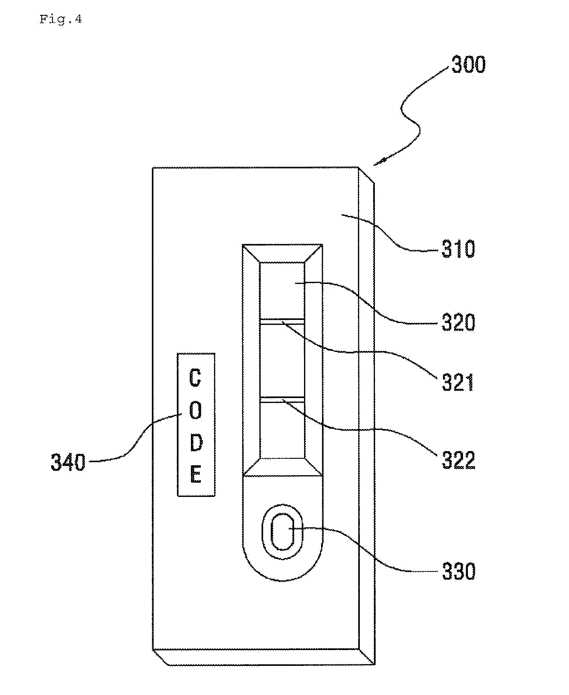
[0057]FIG. 4 is a view illustrating an analyte kit according to the present invention.

[0058]As illustrated in FIG. 4, the analyte kit 300 includes an injection hole 330 for injecting an analyte, a display window 320 display an analysis result of the injected analyte, and an identification code 340.

[0059]In this case, the display window 320 indicates an reaction area where an analyte is reacted.

[0060]To obtain an analyte analysis result using a camera, the display window 320, reaction area, and identification code should be in the same side.

[0061]However since the camera reads the analyte reaction result and identification code separately, the display window 320 and the identification code 340 may be spaced apart by a certain interval.

[0062]And also, the identification code 340 exists in an area of the side of the analyte kit 300, which can be photographed by a camera.

[0063]The identification code 340 may be implemented in various methods, as shown in FIG. 5.

[0064]For example, it may...


PUM


Abstract

The present invention relates to a device and method for quantitatively measuring an analyte using a camera. More particularly, to capture the identification code required for obtaining an accurate analysis result for the analyte to be analyzed, to capture the result of the reaction of the analyte using a camera without additional equipment, and to read the identification code and the result of the reaction of the analyte, the device of the present invention comprises: a camera for capturing a camera recognition area of an analyte kit, which contains an analyte reaction result obtained by the reaction of the analyte and an identification code for the analyte kit; an image-processing unit for separating the analyte reaction result image and the identification code image from images of the camera recognition area of the analyte kit captured by the camera; a reading unit for reading the analyte reaction result image and the identification code image; and a control unit for enabling the read result of the analyte reaction result image to be processed using the read result of the identification code image.

Description

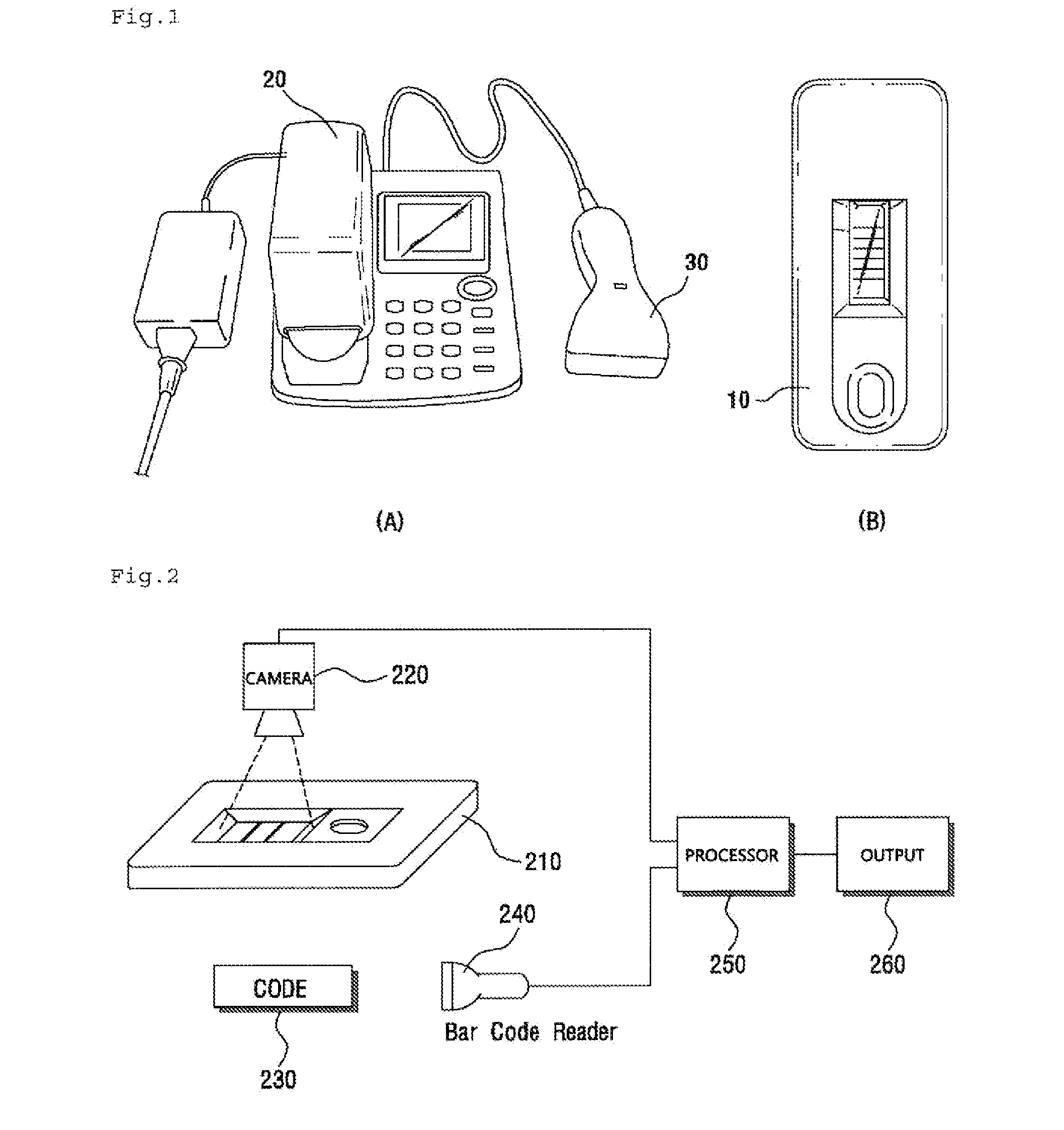
TECHNICAL FIELD[0001]The present invention relates to a device, method, and system for quantitatively measuring an analyte, and more particularly, to a device, method, and system for quantitatively measuring an analyte by using a camera, which can read an identification code required to derive an accurate analysis result of an analyte while photographing an analyte reaction result by using a camera without additional equipment.BACKGROUND ART[0002]In general, as interest in health increases, various technologies for physical health analysis using bio-samples are being introduced.[0003]From thereamong, using diagnostic kits allows an extremely small amount of bio-analytes to be analyzed, thereby easily checking health conditions.[0004]In this case, in order to analyze an end result as illustrated in FIG. 1, a result of an antigen-antibody reaction or enzyme reaction occurring in samples is provided through a diagnostic kit 10, and the result is photographed by a camera 20.[0005]At thi...

Claims


Application Information

Patent Timeline
IPC IPC(8): G01N33/573C12M1/34G01N33/566G01N30/00
CPCG01N21/8483G01N33/558G01N2021/177G01N2333/805G01N33/54388
Inventor BAE, BYEONG-WOOPARK, CHEOL-MIN
Owner OSANG HEALTHCARE CO LTD
Learn More