Electrical connector

a technology of electrical connectors and solder balls, which is applied in the direction of fixed connections, coupling device connections, electrical apparatus construction details, etc., can solve the problems of unaddressed needs in the art, the solder ball has a poor soldering effect, and the clamping effect of the solder ball is lost, so as to achieve the effect of saving production costs, simplifying assembly steps, and improving balance performan

Active Publication Date: 2012-07-12
LOTES
View PDF2 Cites 16 Cited by
  • Summary
  • Abstract
  • Description
  • Claims
  • Application Information

AI Technical Summary

Benefits of technology

[0008]Compared with the related art, among other things, the electrical connector of the present invention is configured such that the first hook and the second hook are formed by extending downwards and then extending laterally from the base, so the distance between the terminals when being unfolded after impact molding is smaller, and thus more terminals can be cut from the terminal material having the same length. Therefore, the terminal material can be used to the maximum extent, thus saving the production cost effectively, and simplifying the assembling steps. The first hook and the second hook are just located at the two opposite sides of the vertical center line of the solder ball, and this structure enables the solder ball to have a better balance performance, thus being firmly hooked in the hooking space without any lateral deviation. As such, the method of disposing two bumps on the insulating body to cooperatively position the solder ball as described in the related art is not required, and it is ensured that the electrical connector has a good soldering effect when being reflowed in the reflow oven without any negative effects such as missing solder. The electrical connector has a simple structure, thus being capable of simplifying the production process and reducing the production cost.

Problems solved by technology

However, when the electrical connector is reflowed in a reflow oven, the insulating body tends to be warped and deformed under heat, thus losing the clamping and positioning effects on the solder ball, such that the solder ball has a poor soldering effect, even missing solder.
Therefore, a heretofore unaddressed need exists in the art to address the aforementioned deficiencies and inadequacies.

Method used


Image

  • Electrical connector
  • Electrical connector
  • Electrical connector

Examples


Embodiment Construction

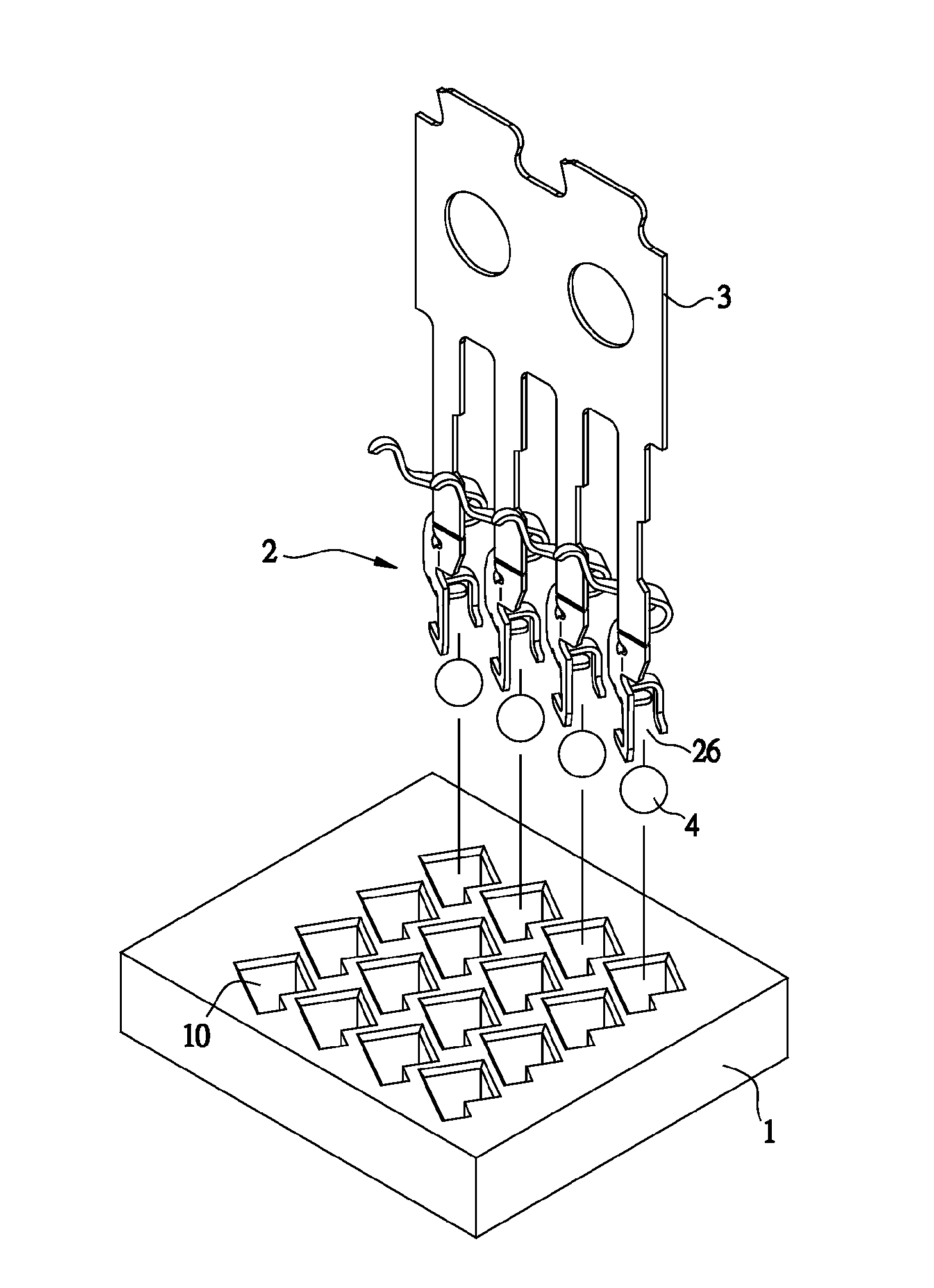
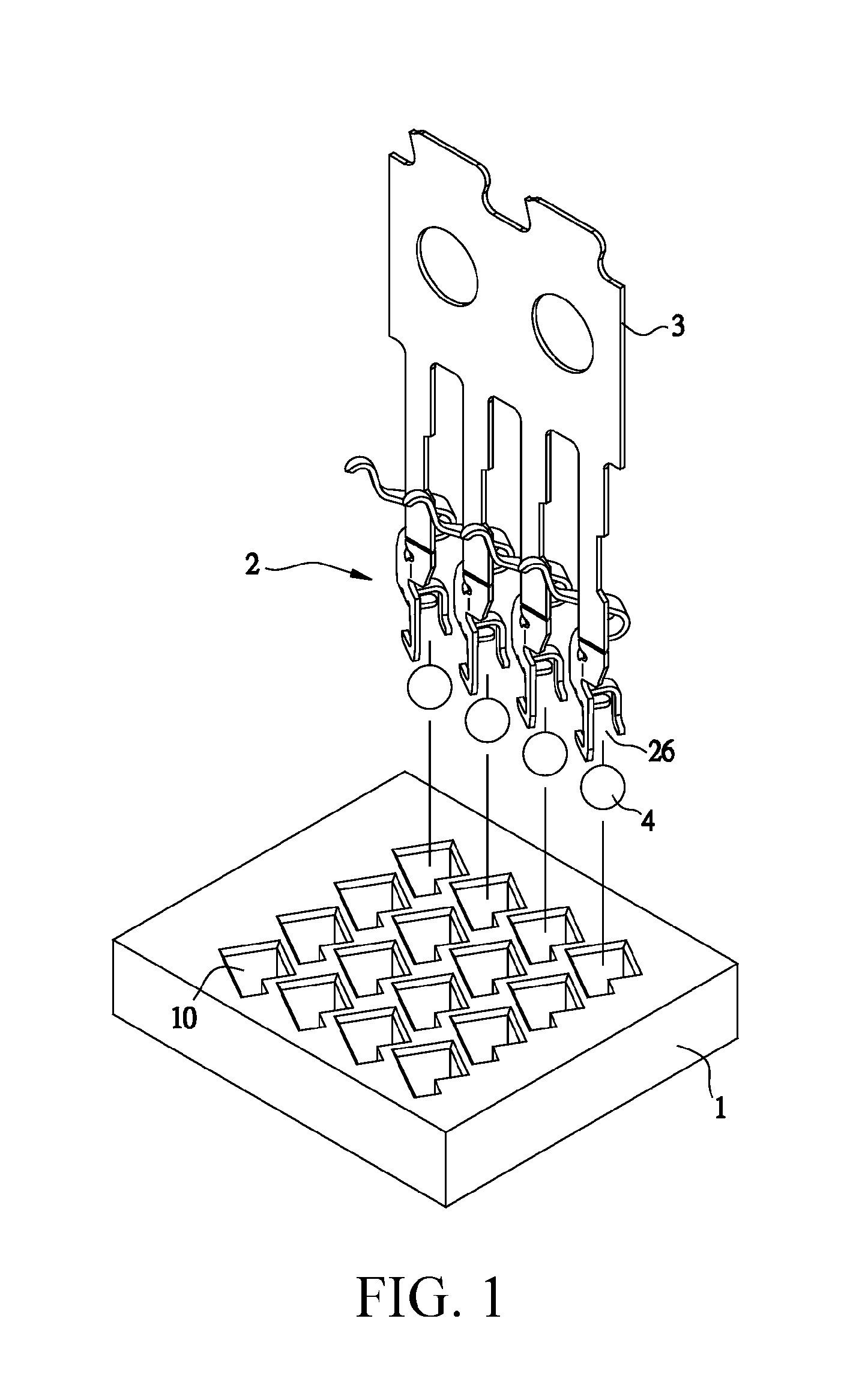
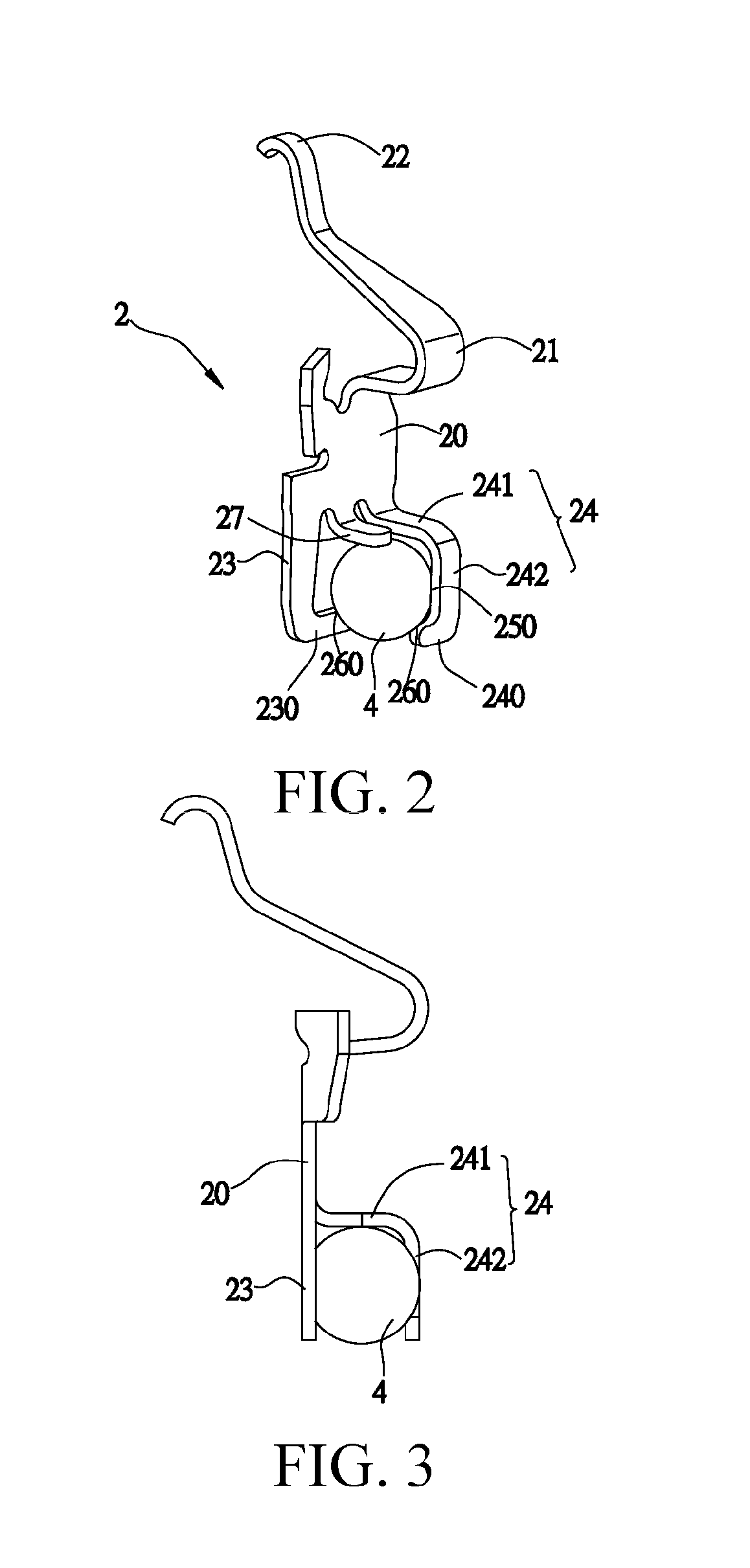
[0016]In order to make the objectives, structure, features and effects of the invention more comprehensible, electronic components and manufacturing methods thereof in the invention are further described below with reference to the accompany drawings and specific embodiments.

[0017]The present invention is more particularly described in the following examples that are intended as illustrative only since numerous modifications and variations therein will be apparent to those skilled in the art. Various embodiments of the invention are now described in detail. Referring to the drawings, FIGS. 1-6, like numbers indicate like components throughout the views. As used in the description herein and throughout the claims that follow, the meaning of “a”, “an”, and “the” includes plural reference unless the context clearly dictates otherwise. Also, as used in the description herein and throughout the claims that follow, the meaning of “in” includes “in” and “on” unless the context clearly dict...


PUM


Abstract

An electrical connector that includes: an insulating body, having a plurality of receiving holes disposed thereon, a plurality of solder balls, respectively received in one of the receiving holes, a plurality of terminals, in which each terminal has a base correspondingly received in one of the receiving holes, a first extending portion and a second extending portion extend downwards from the base, a first hook extends laterally from an end of the first extending portion, a second hook extends laterally from an end of the second extending portion, and the first hook and the second hook respectively hook a periphery of the solder ball under a horizontal center line of the solder ball.

Description

CROSS-REFERENCE TO RELATED APPLICATIONS[0001]This non-provisional application claims priority under 35 U.S.C. §119(a) on Patent Application No. 201120007703.9 filed in The People's Republic of China on Jan. 10, 2011, the entire contents of which are hereby incorporated by reference.FIELD OF THE INVENTION[0002]The present invention relates to an electrical connector, and more particularly to an electrical connector for electrically connecting a chip module to a circuit board.BACKGROUND OF THE INVENTION[0003]Currently, an electrical connector commonly used in the field includes: an insulating body, disposed with a plurality of receiving holes, a plurality of conductive terminals, in which the conductive terminals each have a base fixed in one of the receiving holes, two ball clamping portions respectively extend from the base towards two sides thereof, and the two clamping portions approach each other in a shape of a circle, and a plurality of solder balls, each correspondingly clampe...

Claims


Application Information

Patent Timeline
Patent Type & Authority Applications(United States)
IPC IPC(8): H01R24/00
CPCH01R12/57H05K7/1069H01R12/73
Inventor JU, TED
Owner LOTES
Why Eureka
Try Eureka