Electron Probe Microanalyzer and Data Processing Method Implemented Therein

a technology of electron probe and microanalyzer, which is applied in the direction of material analysis using wave/particle radiation, optical radiation measurement, instruments, etc., can solve the problems of deteriorating reliability of scatter diagram, and long time for obtaining x-ray image data

Active Publication Date: 2012-07-19
JEOL LTD
View PDF15 Cites 9 Cited by
  • Summary
  • Abstract
  • Description
  • Claims
  • Application Information

AI Technical Summary

Benefits of technology

[0022](1) According to the first embodiment of the present invention, in a case where X-ray image data are obtained from the same region at different timings and stored in memory, secondary electron images or backscattered electron images of the region are obtained at the aforementioned timings. The sets of electron image data obtained at the different timings are compared and an amount of positional deviation is calculated. An operation for extracting a region common to regions respectively producing the sets of X-ray image data is performed. Thus, X-ray images of the same region can be obtained even if different sequences of step are performed.
[0023](2) According to the second embodiment, the amount and direction of the positional deviation between the secondary electron images or backscattered electron images indicated by electron image data are calculated by FFT (fast Fourier transform).
[0024](3) According to the third embodiment, a scatter diagram is created based on X-ray image data about a region common to regions respectively producing the extracted sets of X-ray image

Problems solved by technology

Often, it takes long to obtain X-ray image data.
If this is repeated as a sequence of steps, it will take longer to obtain X-ray images.
Therefore, if the regions giving rise to the sets of X-ray image data about the two elements deviate, the reliabili

Method used


Image

  • Electron Probe Microanalyzer and Data Processing Method Implemented Therein
  • Electron Probe Microanalyzer and Data Processing Method Implemented Therein
  • Electron Probe Microanalyzer and Data Processing Method Implemented Therein

Examples


Embodiment Construction

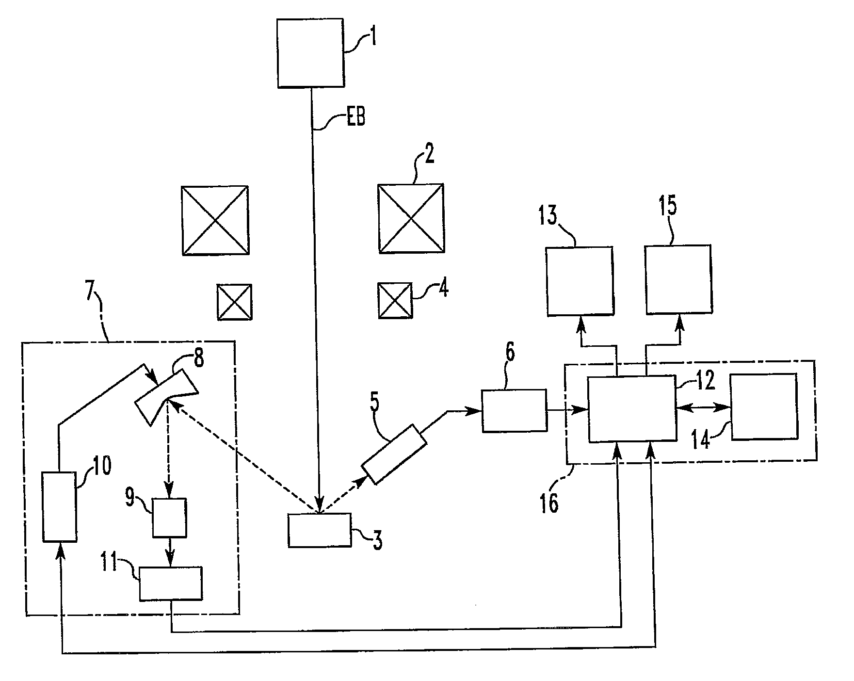
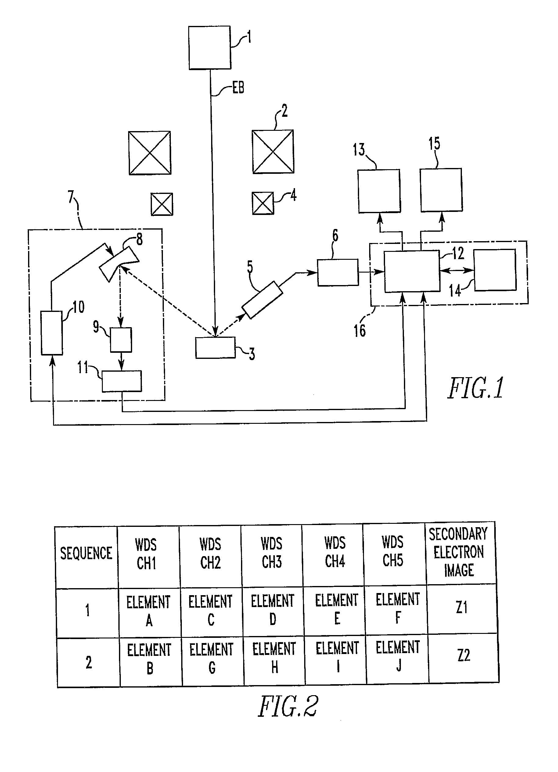
[0031]The preferred embodiments of the present invention are hereinafter described in detail with reference to the drawings. FIG. 1 is a block diagram showing an instrument according to one embodiment of the present invention. This inventive instrument is similar to the related art instrument which has been already described also in connection with FIG. 1 except that secondary electron image data are obtained simultaneously with the acquisition of the X-ray image data in the sequence of steps and stored in memory in association with the sequence of steps and that data processing is performed by the data processing means 14 by utilizing the secondary electron image data. The operation of the instrument according to the invention is described below.

[0032]In FIG. 1, the electron beam EB produced from the electron gun 1 is sharply focused onto the sample 3 by the condenser lens system 2. The beam is scanned over the sample 3 by the beam scan coils 4 or directed at an arbitrary position ...


PUM


Abstract

In an electron probe microanalyzer (EPMA) and a method of use thereof, even if plural sets of X-ray image data are obtained at different timings from regions between which a positional deviation occurs, processing for obtaining the correlation is performed precisely. The sets of X-ray image data are obtained from the same region of a sample using the EPMA at different timings and stored in memory along with sets of electron image data based on detection of secondary or backscattered electrons arising from the region. The sets of electron image data obtained at the different timings are compared, and the amount of positional deviation is calculated. An operation for extracting a region common to the regions respectively producing the sets of X-ray image data obtained at the different timings is performed on these sets of X-ray image data based on the calculated amount of positional deviation.

Description

BACKGROUND OF THE INVENTION[0001]1. Field of the Invention[0002]The present invention relates to an electron probe microanalyzer (EPMA) and, more particularly, to improvements in a method of performing data processing on plural sets of X-ray image data (such as a processing subroutine for creating a scatter diagram) obtained from the same region of a sample.[0003]2. Description of Related Art[0004]In electron probe microanalysis (EPMA), a sample is irradiated with a sharply focused electron beam. The wavelength and strength of characteristic X-rays emanating from the sample are measured by a wavelength-dispersive X-ray spectrometer (WDS). Chemical elements contained in a quite small region of the sample are analyzed qualitatively or quantitatively. By fixing the WDS detection wavelength at the characteristic X-rays of a certain element and scanning the electron beam across the analyzed region of the sample in two dimensions, X-ray image data (mapping data) indicating a distribution ...

Claims


Application Information

Patent Timeline
IPC IPC(8): G01N23/04
CPCG01N23/2251
Inventor OOHASHI, HIDEMI
Owner JEOL LTD
Why Eureka
Try Eureka