LED driving apparatus and LED lighting apparatus

a technology of led lighting and driving apparatus, which is applied in the direction of energy-efficient lighting, sustainable buildings, semiconductor lamp usage, etc., can solve the problems of destabilizing the light emission of led loads, and achieve the effects of reducing current variations, increasing the size and cost of the apparatus, and deteriorating the power conversion efficiency of the apparatus

Active Publication Date: 2012-07-19
SANKEN ELECTRIC CO LTD
View PDF5 Cites 15 Cited by
  • Summary
  • Abstract
  • Description
  • Claims
  • Application Information

AI Technical Summary

Benefits of technology

[0013]FIG. 2 is a waveform diagram illustrating voltages and currents at different parts in the LED driving apparatus 101 and LED lighting apparatus 110 according to the related art illustrated in FIG. 1. The LED driving apparatus 101 converts AC input power into DC power and supplies the DC power to the LED load 102. Accordingly, ripples contained in an input voltage Vin100 easily affect an output voltage Vout100 , i.e. , a voltage across the capacitor C101, and therefore, the output voltage Vout100 involves very small voltage variations. An LED element has a tendency to exponentially increase a forward current (If) as a function of a forward voltage (Vf). Namely, even a very small voltage variation causes a large change in an LED current ILED100 (forward current) passing to the LED load 102. The LED driving apparatus 101 of the related art, therefore, has a problem of easily causing large variations in the LED current ILED100, to destabilize light emission of the LED load 102. Such current variations may be reduced by increasing capacitance of the capacitor C101. This, however, requires a large-sized electrolytic capacitor, to increase the size of the LED lighting apparatus 110.
[0016]The LED driving apparatus of FIG. 3 employs the power factor corrector in addition to the power converter, and therefore, is capable of carrying out highly efficient power conversion. In addition, it can reduce ripples in an AC input voltage through two stages including the power factor corrector that provides an output voltage Vout1 and the power converter that provides an output voltage Vout2, thereby minimizing current ripples to be passed through an LED load 102.
[0019]This LED driving apparatus is capable of reducing variations in a current passed to the LED load and stabilizing light emission of the LED load. This LED driving apparatus, however, must have the two converters, i.e., the AC / DC converter and DC / DC converter, to increase the size and cost of the apparatus and deteriorate the power conversion efficiency of the apparatus.
[0020]The present invention provides an LED driving apparatus that is compact and capable of stabilizing light emission of an LED load and an LED lighting apparatus employing the LED driving apparatus.
[0021]According to an aspect of the present invention, the LED driving apparatus converts AC input power into predetermined DC output power and supplies the DC output power to an LED load. The LED driving apparatus includes a switching element to be turned on and off, a ripple current reducer that is connected in series with the LED load and reduces current ripples of the LED load, and a controller that turns on and off the switching element according to a feedback voltage at a connection point of the LED load and ripple current reducer, thereby controlling the DC output power to the predetermined value.

Problems solved by technology

The LED driving apparatus 101 of the related art, therefore, has a problem of easily causing large variations in the LED current ILED100, to destabilize light emission of the LED load 102.

Method used


Image

  • LED driving apparatus and LED lighting apparatus
  • LED driving apparatus and LED lighting apparatus
  • LED driving apparatus and LED lighting apparatus

Examples


first embodiment

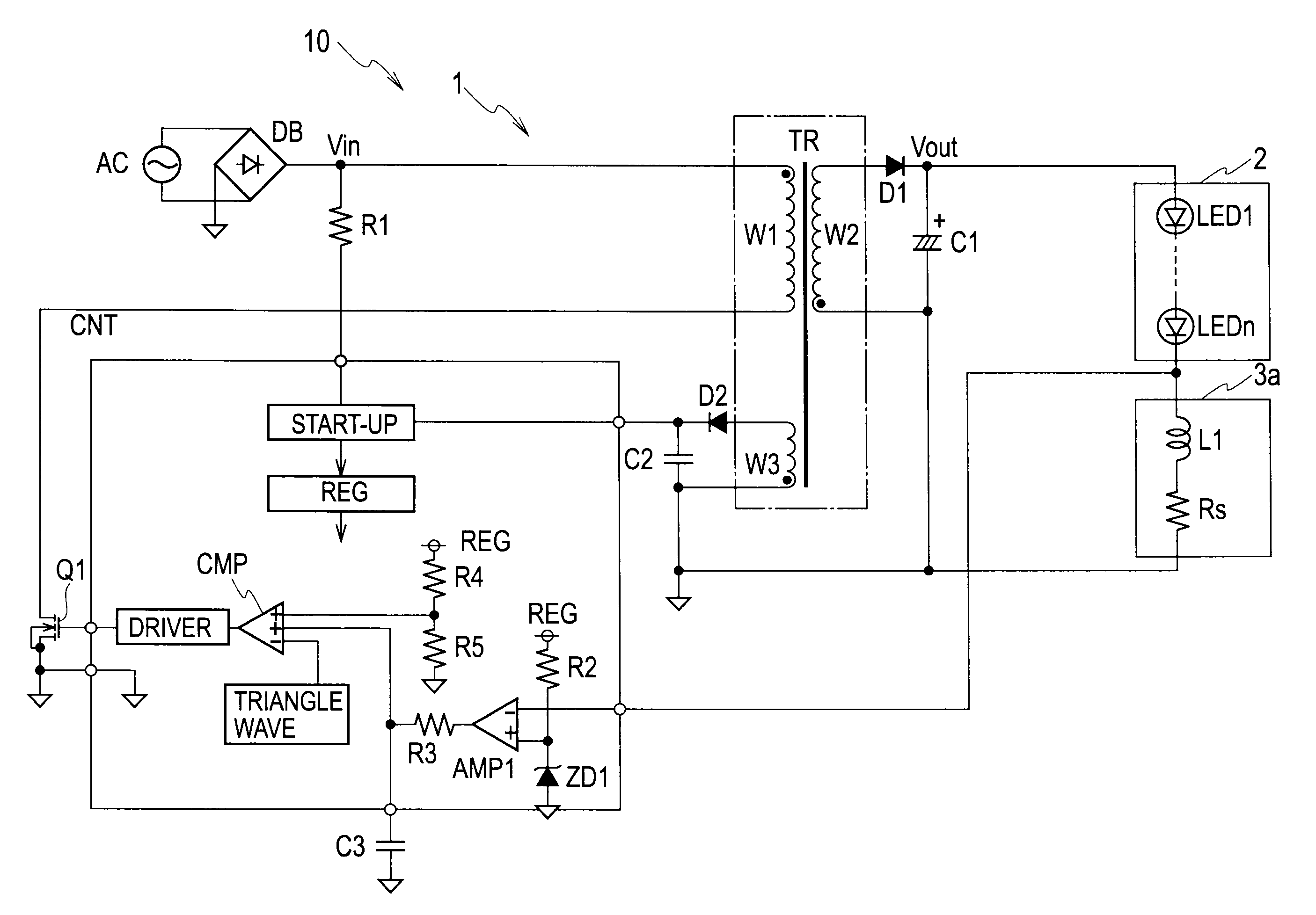
[0029]FIG. 4 is a circuit diagram illustrating an LED lighting apparatus 10 with an LED driving apparatus 1 according to the first embodiment of the present invention. The LED driving apparatus 1 includes a rectifier DB, a transformer TR, a first MOSFET (switching element) Q1, a rectifying-smoothing circuit including a diode D1 and a capacitor C1, a controller CNT, a capacitor C3, and a ripple current reducer 3a. The LED driving apparatus 1 and an LED load 2 having LED elements LED1 to LEDn form the LED lighting apparatus 10.

[0030]The rectifier DB is a known diode bridge and is connected to an AC input power source AC, to rectify AC input power into a pulsating current of one direction and supply the current to the transformer TR. The AC input power source AC and rectifier DB may be replaced with a DC power source such as a battery.

[0031]The transformer TR has a primary winding W1, a secondary winding W2, and a tertiary winding W3. A first end of the primary winding W1 is connected ...

second embodiment

[0042]FIG. 6 is a circuit diagram illustrating an LED lighting apparatus 10 with an LED driving apparatus 1 according to the second embodiment of the present invention. The second embodiment of FIG. 6 differs from the first embodiment of FIG. 4 in the configuration of the ripple current reducer.

[0043]In FIG. 6, the ripple current reducer 3b according to the present embodiment is connected to a rectifying-smoothing circuit including a diode D1 and a capacitor C1, an LED load 2, and a controller CNT. The ripple current reducer 3b is a voltage-controlled current source and corresponds to the feedback-controlled constant current source as stipulated in the claims. The ripple current reducer 3b includes a second MOSFET (variable impedance element) Q2, a detective resistor (current detector) Rs, a second error amplifier AMP2, and a zener diode ZD2. A drain of the second MOSFET Q2 is connected to a cathode of an LED element LEDn of the LED load 2, a source thereof is connected through the ...


PUM


Abstract

An LED driving apparatus converts AC input power into predetermined DC output power and supplies the DC output power to an LED load. The LED driving apparatus includes a switching element Q1 to be turned on and off, a ripple current reducer 3a that is connected in series with the LED load and reduces current ripples of the LED load, and a controller CNT that turns on and off the switching element according to a feedback voltage taken from a connection point of the LED load and ripple current reducer, thereby controlling the DC output power to a predetermined value.

Description

BACKGROUND OF THE INVENTION[0001]1. Field of the Invention[0002]The present invention relates to an LED driving apparatus and an LED lighting apparatus employing the LED driving apparatus.[0003]2. Description of Related Art[0004]LED (light emission diode) elements are used for backlights of liquid crystal displays and light sources of lighting devices such as streetlights. Incandescent bulbs and fluorescent lamps are being replaced with bulb-type LED lighting apparatuses and fluorescent-lamp-type LED lighting apparatuses using white LED elements. These LED lighting apparatuses need LED driving apparatuses that are capable of correctly supplying electric power to the LED elements.[0005]FIG. 1 is a circuit diagram illustrating an LED lighting apparatus 110 having an LED driving apparatus 101 according to a related art. The LED driving apparatus 101 includes a rectifier DB100, a transformer TR100, a switching element MOSFET Q101, a rectifying-smoothing circuit including a diode D101 an...

Claims


Application Information

Patent Timeline
Patent Type & Authority Applications(United States)
IPC IPC(8): H05B37/02H05B44/00
CPCY02B20/30H05B45/385Y02B20/72H05B45/37
Inventor KIMURA, KENGOHIRATA, KAZUSHIGENAKANO, TOSHIHIRO
Owner SANKEN ELECTRIC CO LTD
Why Eureka
Try Eureka