
Detection device, detection system and detection method of radio wave transmitting/receiving body

Active Publication Date: 2012-07-19
OMRON AUTOMOTIVE ELECTRONICS CO LTD
View PDF11 Cites 15 Cited by
  • Summary
  • Abstract
  • Description
  • Claims
  • Application Information

AI Technical Summary

Benefits of technology

[0010]One or more embodiments of the present invention provides a detection system, a detection device and a detection method that prevent undetection of a portable machine as a key including a specific identification code and a communication function, which portable machine is left in an area or in a space to be protected by locking (hereinafter, referred to as a “specific space”). One or more embodiments of the present invention provides a detection system, a detection device and a detection method that prevent false detection that the key exists inside the specific space although the key exists outside the specific space.
[0033]As described above, according to one or more embodiments of the present invention, the detection system, the detection device and the detection method can be provided that prevent the undetection of the key existing inside the specific space, the key having the specific identification code and the communication function, and prevent the false detection of the key outside the specific space.

Problems solved by technology

However, in some cases, in the detection of the portable machine in an area or in a space to be protected by the locking (e.g., inside a vehicle, inside a building / room, inside a locker), the portable machine cannot be detected although it exists in the area or in the space, or it is detected in the wrong although it does not exist in the area or space.

Method used


Image

  • Detection device, detection system and detection method of radio wave transmitting/receiving body
  • Detection device, detection system and detection method of radio wave transmitting/receiving body
  • Detection device, detection system and detection method of radio wave transmitting/receiving body

Examples


first embodiment

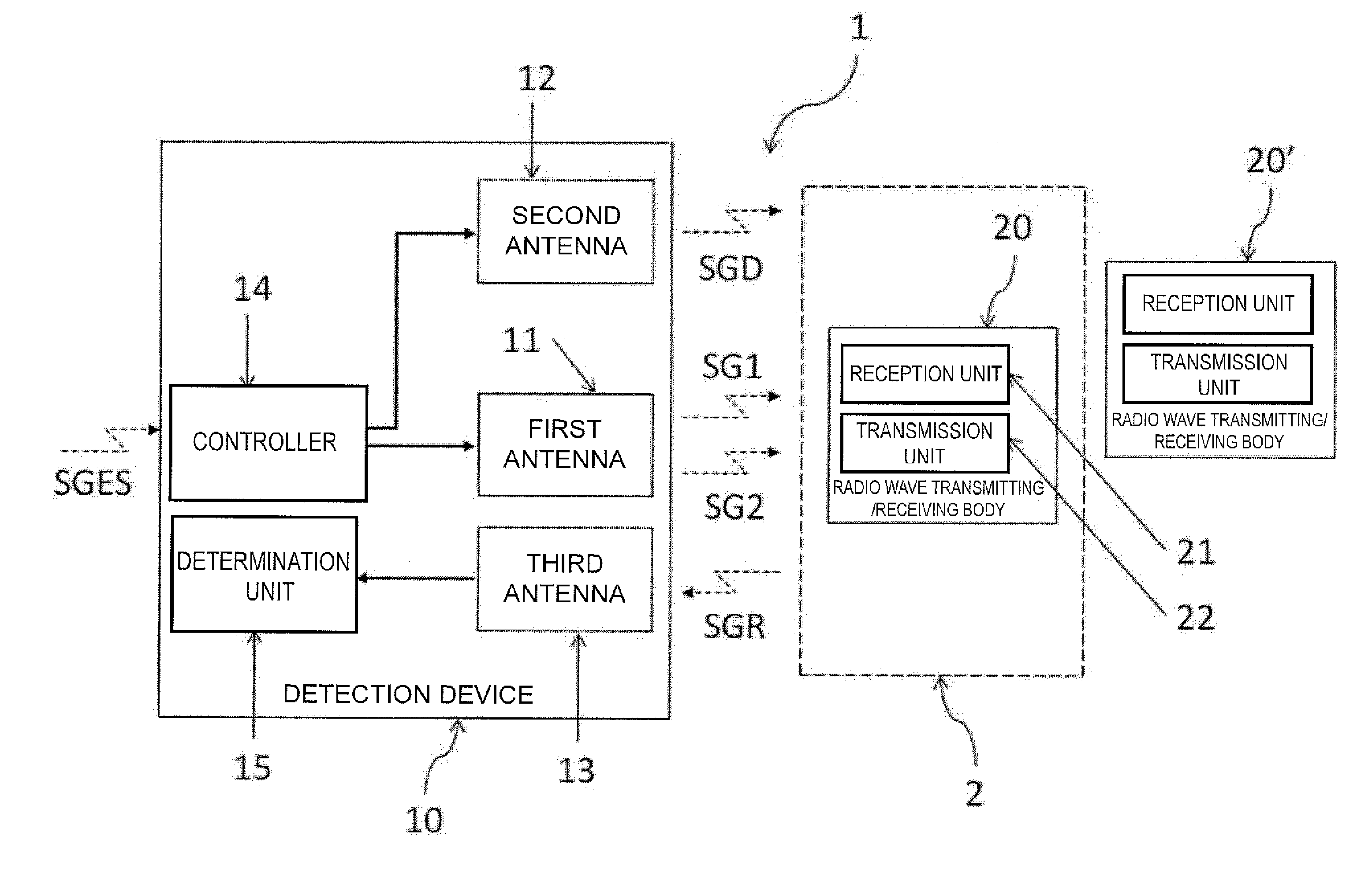
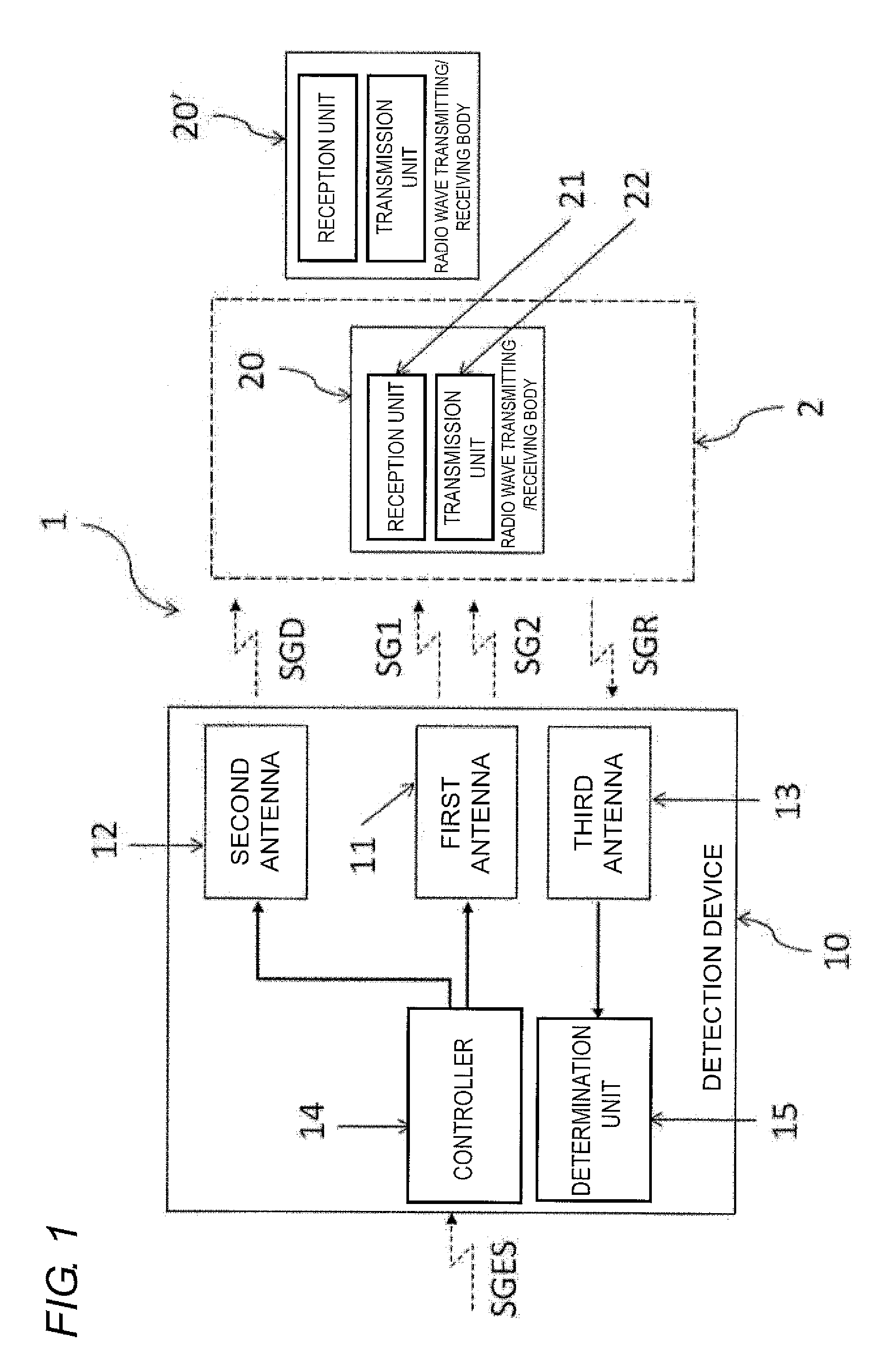
[0046]FIG. 1 shows a basic configuration of a detection system 1 of a first embodiment of the present invention. The detection system 1 includes a radio wave transmitting / receiving body 20 having a specific identification code, and a detection device 10 to detect existence of this radio wave transmitting / receiving body 20.

[0047]The radio wave transmitting / receiving body 20 includes a reception unit 21 that receives a first detection signal and a second detection signal transmitted by the detection device 10, a transmission unit 22 that transmits a response signal to the received first detection signal and second detection signal, and when the detection signal transmitted by the detection device 10 is received, the response signal is transmitted to the detection signal together with the specific identification code.

[0048]The detection device 10 transmits the detection signal. The radio wave transmitting / receiving body 20, which has received the detection signals, transmits the respon...

second embodiment

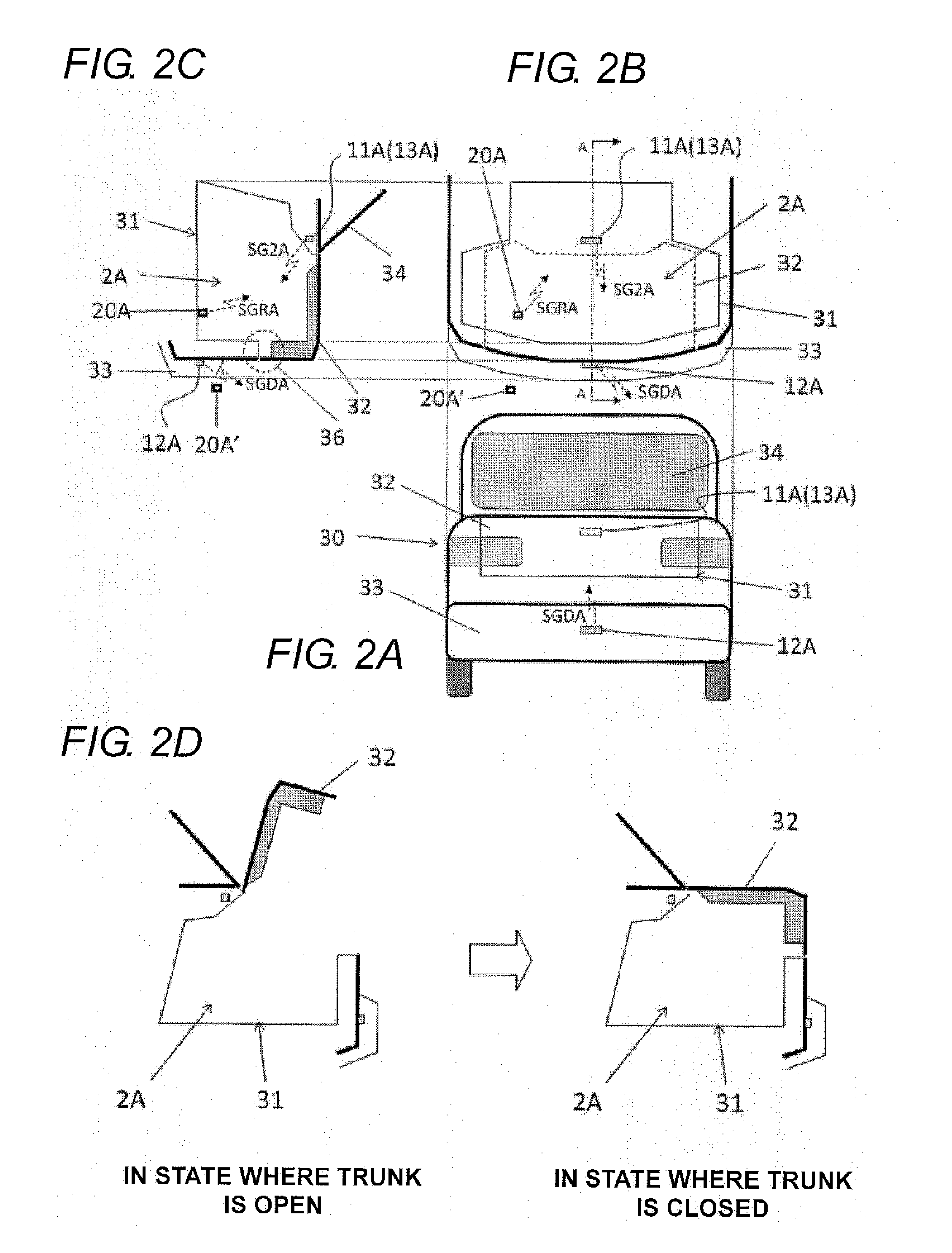
[0063]FIGS. 2A to 2C show one or more embodiments of the present invention, in which the detection device according to one or more embodiments of the present invention is applied to a trunk of a vehicle. That is, the specific space is an internal space 2A of a trunk 31 of a vehicle 30, and the radio wave transmitting / receiving body is a portable machine 20A (20A′) that transmits a signal to close or open a latch mechanism of the trunk 31. That the specific space 2A becomes a closed space means that the trunk of the vehicle is put into a closed state from an open state, as shown in FIG. 2D, that is, a trunk lid 32 is closed from an open state, thereby putting the latch mechanism into a locked state.

[0064]A second antenna 12A is attached almost in a lateral center of a rear bumper 33 outside the vehicle 30. A first antenna 11A is attached anterior to the rear bumper 33 above the trunk 31, almost in a lateral center of a vehicle interior below a rear glass 34. The first antenna 11A and...

third embodiment

[0084]FIG. 8 shows a flowchart regarding an embodiment of a detection method for detecting the existence of the radio wave transmitting / receiving body inside the specific space, according to one or more embodiments of the present invention. In the flowchart, “S” denotes a step of processing.

[0085]First, as the first step, it is detected that a specific space 2B, which is a space to be protected by locking, has become a closed space (S100). Following the expression in the second embodiment, it is detected that the trunk lid is closed (the latch mechanism is put into the locked state).

[0086]Next, as the second step, a first detection signal SG1B and a second detection signal SG2B are transmitted at different timing, and a disturbing signal SGDB to cancel a part of the second detection signal SG2B is transmitted simultaneously with the second detection signal SG2B (S200). While in the present figure, the first detection signal SG1B is transmitted (S210) and then, the second detection s...


PUM


Abstract

A detection device that detects existence of a radio wave transmitting / receiving body inside a specific space has a first antenna, a second antenna, a controller that controls a first detection signal and a second detection signal that the first antenna transmits to an inside of the specific space, and a disturbing signal that the second antenna transmits, a third antenna that receives a response signal transmitted to the first detection signal and the second detection signal, which have been received by the radio wave transmitting / receiving body, and a determination unit that determines an existence position of the radio wave transmitting / receiving body, based on the response signal received by the third antenna.

Description

BACKGROUND OF THE INVENTION[0001]1. Technical Field[0002]The present invention relates to a detection device, a detection system and a detection method of a radio wave transmitting / receiving body, and particularly to a detection device, a detection system, and a detection method that detect existence of a radio wave transmitting / receiving body in order to prevent a situation where locking is performed, leaving the radio wave transmitting / receiving body in a specific space, so-called containment.[0003]2. Related Art[0004]Recently, an automatic locking function has often been employed to increase assurance and convenience of locking in a vehicle, a building, a locker or the like. Particularly, as represented by a trunk of the vehicle, a mechanism that automatically performs locking at the same time as closing of a door or the like has often been employed. On the other hand, when a key necessary for unlocking is left indoors, a spare key, a specialist for unlocking or the like is neede...

Claims


Application Information

Patent Timeline
IPC IPC(8): G08B29/00H04W4/00B60R25/01B60R25/24B60R25/30E05B49/00G01S13/74
CPCH04W52/283H04B17/27G07C2209/63B60R25/245B60R25/10E05B49/00E05B81/64H04B1/38
Inventor NISHIGUCHI, TADAO
Owner OMRON AUTOMOTIVE ELECTRONICS CO LTD
Learn More