Projector

Active Publication Date: 2012-07-19
SEIKO EPSON CORP
View PDF5 Cites 20 Cited by
  • Summary
  • Abstract
  • Description
  • Claims
  • Application Information

AI Technical Summary

Benefits of technology

[0008]An advantage of some aspects of the invention is to provide

Problems solved by technology

However, since laser light is coherent light, speckles which occur due to interference are displayed on a screen, which causes the display quality to be lowered.
However, it is difficult to sufficiently suppress s

Method used


Image

  • Projector
  • Projector
  • Projector

Examples


Example

First Embodiment

[0051]An embodiment of a projector according to the invention will be described with reference to FIGS. 1 to 6.

[0052]In the present embodiment, a projection type projector which projects color light including image information generated by a light modulation device on a screen (a projection surface) through a projection optical system will be described as an example of a projector 1.

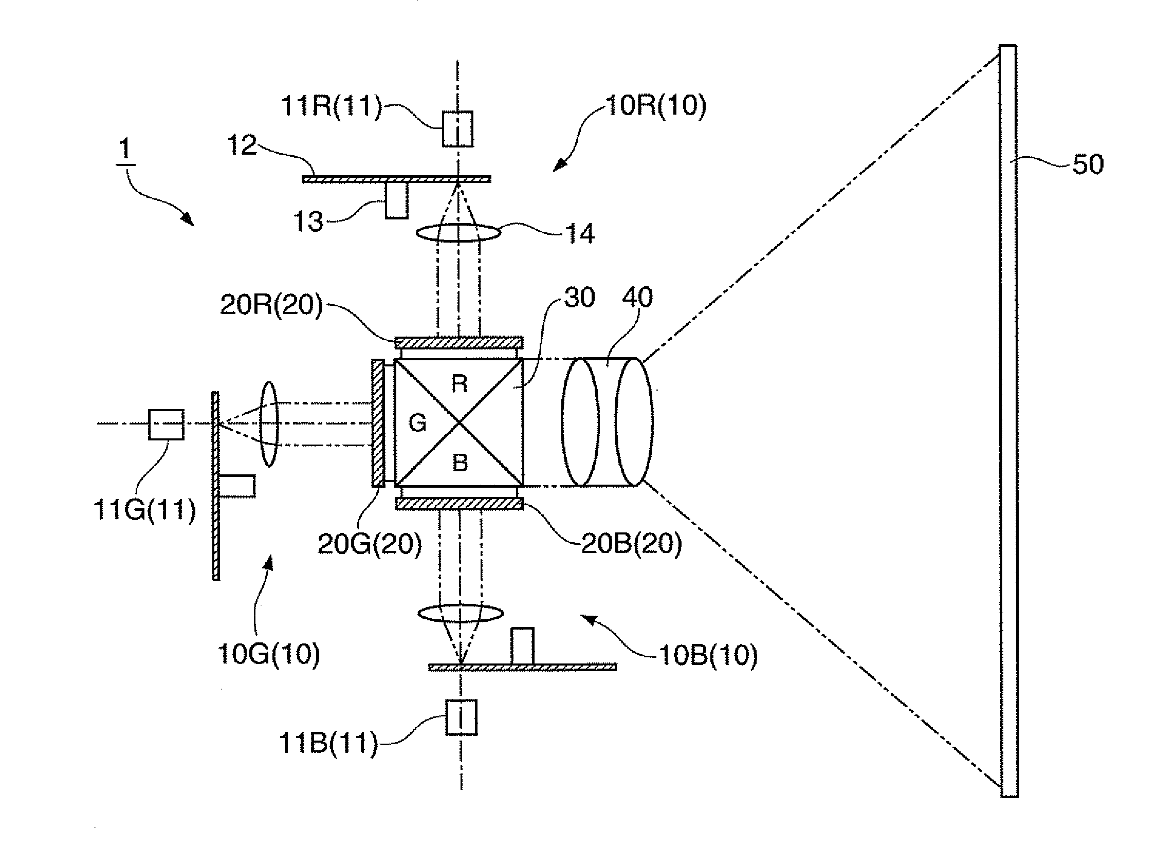
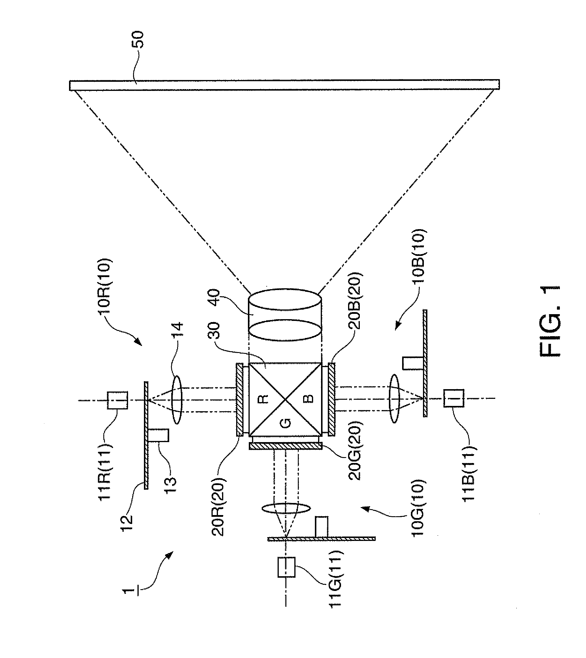
[0053]As shown in FIG. 1, the projector 1 includes a light source device 10, a light modulation device 20, a dichroic prism 30, and a projection optical system 40.

[0054]The light source device 10 includes a red light source device 10R which emits red light, a green light source device 10G which emits green light, and a blue light source device 10B which emits blue light.

[0055]The light modulation device 20 includes a two-dimensional red light modulation device 20R which modulates the light emitted from the red light source device 10R according to the image information, a two-dimensional g...

Example

[0113]FIG. 10 is a diagram schematically illustrating a projector 2 according to a second embodiment of the invention, corresponding to FIG. 1.

[0114]As shown in FIG. 10, the projector 2 according to the present embodiment is different from the projector 1 according to the above-described first embodiment in that a polarizing beam splitter 130 is disposed on an optical path between the light source device 10 and the dichroic prism 30 and a light modulation device 320 is a reflection type liquid crystal light valve. Since other configurations are the same as the above-described configurations, the same reference numerals are given to the same elements as in FIG. 1, and detailed description thereof will be omitted.

[0115]As shown in FIG. 10, the projector 2 includes the light source device 10, the polarizing beam splitter 130, the light modulation device 320, the dichroic prism 30 and the projection optical system 40.

[0116]The polarizing beam splitter 130 includes a red polarizing beam ...

Example

Third Embodiment

[0131]FIG. 13 is a diagram schematically illustrating a projector 3 according to a third embodiment of the invention, corresponding to FIG. 11.

[0132]As shown in FIG. 13, the projector 3 according to the present embodiment is different from the projector 2 according to the above-described second embodiment in that a micromirror type light modulation device 520 is disposed on an optical path between the light source device 10 and the dichroic prism 30. Since other configurations are the same as the above-described configurations, the same reference numerals are given to the same elements as in FIG. 11, and detailed description thereof will be omitted.

[0133]As shown in FIG. 13, the projector 3 includes the light source device 10, the light modulation device 520, the dichroic prism 30 and the projection optical system 40.

[0134]FIG. 14 is a diagram schematically illustrating the light modulation device 520 according to the third embodiment.

[0135]As shown in FIG. 14, the l...


PUM


Abstract

A projector includes: a light source which emits laser light; a first diffusing section which diffuses the laser light emitted from the light source to emit a first diffused light; and a light modulation device which modulates the first diffused light emitted from the first diffusing section. The light modulation device includes a second diffusing section which diffuses the first diffused light emitted from the first diffusing section to emit a second diffused light, and diffusion intensity distribution of the second diffused light emitted from the second diffusing section is distribution which is consecutive around a central axis of the second diffused light.

Description

BACKGROUND[0001]1. Technical Field[0002]The present invention relates to a projector.[0003]2. Related Art[0004]As a light source for a projector, a laser light source which is capable of obtaining high output light has gained attention. The laser light source has advantages such as superior color reproducibility, easier instant lighting and longer lifespan compared with a high pressure mercury lamp. However, since laser light is coherent light, speckles which occur due to interference are displayed on a screen, which causes the display quality to be lowered.[0005]Technologies for solving this problem have been studied. For example, in a projector disclosed in JP-A-2010-197916, characteristics and arrangement of a light modulation device are set so that a light distribution angle with regard to one arbitrary point on a screen is equal to or larger than a predetermined angle. It is known that if the light distribution angle becomes large, it is possible to suppress lowering of the dis...

Claims


Application Information

Patent Timeline
IPC IPC(8): G03B21/14
CPCG02B5/0215G02B5/0278G03B21/2053G03B21/2013G02F1/133526
Inventor OTANI, MAKOTO
Owner SEIKO EPSON CORP
Why Eureka
Try Eureka