Molten salt nuclear reactor

a nuclear reactor and molten salt technology, applied in nuclear reactors, thermal reactors, nuclear energy generation, etc., can solve the problems of high cost and complex technique of contacting the fuel salt, difficult fission products, and difficult to extract liquid bismuth

Inactive Publication Date: 2012-07-19
OTTAWA VALLEY RES ASSOCS
View PDF0 Cites 28 Cited by
  • Summary
  • Abstract
  • Description
  • Claims
  • Application Information

AI Technical Summary

Benefits of technology

[0037]It is an object of the present invention to obviate or mitigate at least one disadvantage of previous molten salt nuclear reactors.
[0041]In a further embodiment, the breeding section surrounds the fuel salt conduit to maximize the probability of capture by the fertile elements of the breeding section of the neutrons generated in the elongated nuclear core section.

Problems solved by technology

Liquid Bismuth Extraction: an often expensive and complex technique of contacting the fuel salt with liquid bismuth to remove fission products, protactinium and / or transuranics.
However, it was recognized that the presence of thorium in the fuel salt would make processing for fission products problematic as thorium behaves chemically much like the important rare earth fission products, which makes it very difficult to remove fission products without also removing the thorium.
Nevertheless, due to the absence of thorium in the core region, there was still the problem of the upper limit of power density within the core region due to the neutron induced swelling of the graphite.
That is, the volume of the core would have had a maximum value beyond which the reactor was super-critical, but this maximum volume was still too small to provide a useful output power.
This meant that the critical concentration needed for 233UF4 would be so low that parasitic neutron absorption in the carrier salt and graphite would have dominated and rendered breeding virtually impossible.
As adding any metal would be detrimental to breeding ratios because of neutron absorption, the use of graphite itself as the plumbing material became the focus of such breeder reactors.
However, the behavior of graphite under radiation (shrinking and then swelling) proved to be a major hurdle since a changing tube diameter would mean a changing volume of blanket salt between tubes, which adversely affects reactivity.
Another issue with this Two-Fluid design is that the blanket salt would have positive temperature or void reactivity coefficients, which runs counter to standard design practice.
This Two-Fluid reactor design was eventually dismissed after many years effort.
This arrangement results in under moderation and leads to the outer annulus being a net absorber of neutrons, which acts to lower the percentage of neutrons lost by leakage; however, the neutron loss is still an order of magnitude larger than for the previous Two-Fluid reactors.
While the advent of the Liquid Bismuth Extraction technique allowed a new method of fission product processing, it was by no means a simple process.
The removal of fission products with thorium present is possible but it does make the process much more complex as thorium behaves chemically much like the important rare earth fission products.
Another issue with prior art molten salt reactor relates to their limited ability to burn transuranic (TRU) waste produced by, for example, light water reactors (LWRs).
In several studies however, the limited solubility of PuF3 and the other tri-fluoride TRUs has lead to difficulties.
However these studies with NaF—ZrF4 have concluded that the concentration of TRUs in the fuel salt cannot be maintained high enough to keep those prior art molten salt reactors critical, even with rapid fission product removal.
As well, in these proposals, the destruction of TRUs is never really complete due to the fact that at the end of the reactors lifetime, there still exists up to several tonnes of TRUs in the salt.
This limited reactivity problem only occurs after several months of operation, which is due to the fact that the initial fissile to fertile ratio in LWR wastes is quite high, but drops significantly as it is fissioned in a TRU burner reactor.
Processing of the fuel salt is thus complicated by the presence of Pu and the other trans-plutonium elements.
As well, even though LEU is probably only needed for the initial specific inventory, it would take years, if not decades to burn off the 238U and the transuranics it produces.
The issue of operating prior art MSNRs on denatured uranium for the lifetime of the reactor was either never seriously considered or, in the case of Single-Fluid graphite moderated reactors, deemed to be barely able to attain a break even breeding ratio.

Method used


Image

  • Molten salt nuclear reactor
  • Molten salt nuclear reactor
  • Molten salt nuclear reactor

Examples


Embodiment Construction

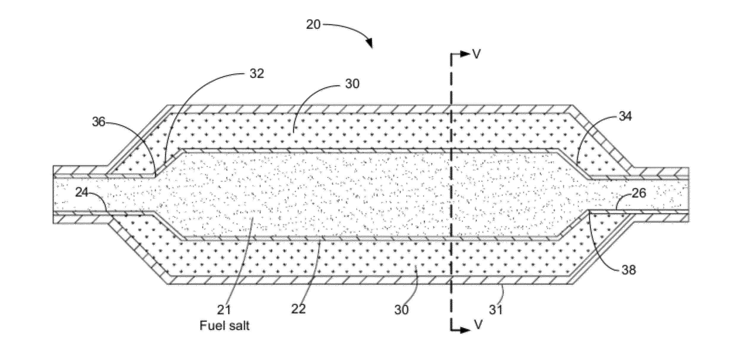
[0088]Generally, the present invention provides a molten salt nuclear reactor having an elongated core section in which criticality is achieved. The power producing volume of the elongated core section is such that considerably more power can be extracted in comparison with prior art molten salt nuclear reactors.

[0089]FIGS. 4 and 5 show an exemplary embodiment of a reactor core assembly 20 of the present invention. The reactor core assembly 20 has a fuel salt conduit 22 that has an input end section 24, an output end section 26 and an elongated core section 28, which is for guiding a molten fuel salt between the input end section 24 and the output end section 26. The dimensions of the elongated core section are chosen such that for a molten fuel salt having a pre-determined concentration of fissile elements, criticality is reached within the elongated core section. That is, the area of the cross-section (FIG. 5) of the elongated core section 28 and the length of the elongated core s...


PUM


Abstract

A molten salt breeder reactor that has fuel conduit surrounded by a fertile blanket. The fuel salt conduit has an elongated core section that allows for the generation of electrical power on a scale comparable to commercially available nuclear reactors. The geometry of the fuel conduit is such that sub-critical conditions exist near the input and output of the fuel salt conduit and the fertile blanket surrounds the input and output of the fuel salt conduit, thereby minimizing neutron losses.

Description

CROSS REFERENCE TO RELATED APPLICATIONS[0001]This application is a continuation of U.S. patent application Ser. No. 12 / 118,118, filed May 9, 2008, which is incorporated herein by reference in its entirety.FIELD OF THE INVENTION[0002]The present invention relates generally to nuclear reactors. More particularly, the present invention relates to molten salt nuclear reactors.BACKGROUND OF THE INVENTION[0003]The following is a list of definitions of terms used herein:[0004]Carrier Salt: a salt added to fissile and / or fertile salts. The purpose of the carrier salt is primarily to form a low melting point eutectic with good thermodynamic and neutronic properties. An example of a well-known carrier salt is 27LiF—BeF2 [0005]Fuel Salt: a molten salt containing fissile material such as, for example, 233UF4, 235UF4, and PuF3. It can also contain fertile material such as, for example, ThF4 or 238UF4.[0006]Blanket Salt: a molten salt containing fertile material such as, for example, ThF4 .[0007]...

Claims


Application Information

Patent Timeline
Patent Type & Authority Applications(United States)
IPC IPC(8): G21G1/06
CPCG21C1/22Y02E30/40G21C5/126G21C3/22Y02E30/30
Inventor LEBLANC, DAVID
Owner OTTAWA VALLEY RES ASSOCS
Why Eureka
Try Eureka