Display apparatus and process for producing the same

a technology for display apparatuses and process steps, applied in the direction of film/foil adhesives, other chemical processes, instruments, etc., can solve the problem of insufficient mechanical strength, and achieve the effect of suppressing the formation of air bubbles, and less susceptible to breakag

Inactive Publication Date: 2012-07-19
ASAHI GLASS CO LTD
View PDF1 Cites 13 Cited by
  • Summary
  • Abstract
  • Description
  • Claims
  • Application Information

AI Technical Summary

Benefits of technology

[0051]According to the process for producing a display apparatus of the present invention, the display device can be made to be less susceptible to breakage, and the interface bonding strength between a resin layer and the display device and the interface bonding strength between the resin layer and a transparent plate can be increased, while sufficiently suppressing formation of air bubbles in a liquid curable resin composition.
[0052]The display apparatus of the present invention is less susceptible to breakage, and has a high interface bonding strength between the resin layer and the display device and a high interface bonding strength between the resin layer and the transparent plate, and formation of air bubbles remained in its resin layer is sufficiently suppressed. Particularly, the present invention is excellent in terms of the capability for bonding in a good flatness a transparent plate to a display device having a large area such as a large-sized liquid crystal device.

Problems solved by technology

Particularly, a display apparatus has been known in which a protective plate made of the transparent plate is provided on a display device having an insufficient mechanical strength due to the thin thickness of a substrate on the display surface side of the display device.

Method used


Image

  • Display apparatus and process for producing the same
  • Display apparatus and process for producing the same
  • Display apparatus and process for producing the same

Examples


specific examples

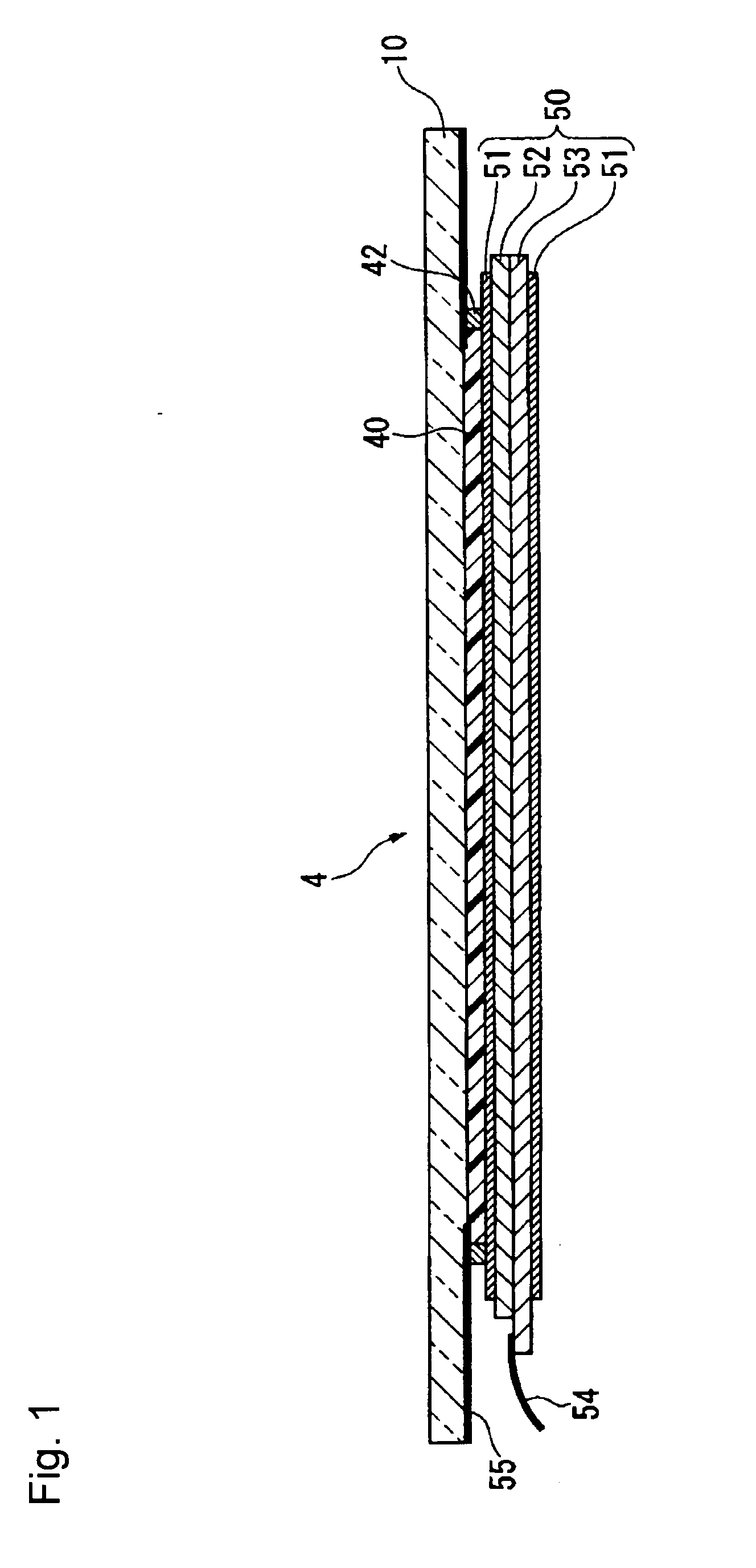
[0165]In the production process of the present invention, it is optional to use the back plate or the front plate as the first plate. Accordingly, the display apparatus can be produced by the following two methods, depending upon the selection of the first plate.

[0166](A-1) A method of using a display device (the back plate) as the first plate, and a transparent plate 10 (the front plate) for a protective plate as the second plate.

[0167](A-2) A method of using a transparent plate 10 (the front plate) for a protective plate as the first plate, and a display device (the back plate) as the second plate.

[0168]Now, taking the case of the method (A-1) as an example, the process for producing a display apparatus will be described in detail with reference to the drawings. Further, in FIGS. 3 to 8, examples wherein a double-sided adhesive tape is used in the seal part formed on the edge of the first plate as a sealing material are illustrated.

(Step (a))

[0169]As shown in FIGS. 3 and 4, a doub...

example 1

[0187]A liquid crystal display device was removed from a commercially available 32-inch liquid crystal television receiver (HDV-32WX2D-V, manufactured by PC DEPOT CORPORATION). The liquid crystal display device was found to have a long side length of 712 mm, a short side length of 412 mm and a thickness of about 2 mm. Both sides of the liquid crystal display device were found to be bonded to polarizing plates, and 6 FPCs for driving were found to be bonded to one side of the long side, and then printed circuit board was found to be bonded to the edge of each FPC. The image display portion was found to have a long side length of 696 mm, and a short side length of 390 mm. Then, such a liquid crystal display device was designated as display device G.

[0188]On a peripheral portion of one surface of soda lime glass having a long side length of 794 mm, a short side length of 479 mm and a thickness of 3 mm, a light-shielding printing part was formed in a frame-like shape by printing with a ...

example 2

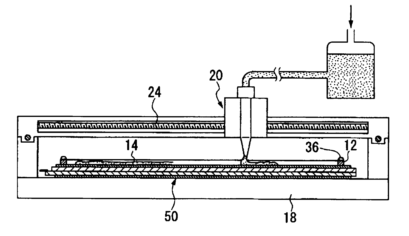
[0202]To the edge of the display device G, a double-sided adhesive tape having a thickness of 0.5 mm and a width of 2 mm was bonded, and while leaving the release film of the double-sided adhesive tape only along one side, the release film on the surface was peeled. On the glass plate H, the display device G was laminated and bonded by the double-sided adhesive tape along the three sides.

[0203]On one side where the release film was left, the space between the double-sided adhesive tape and the display device G was forced open for about 2 mm by a screw driver, and it was attempted to inject 155 g of the photocurable resin composition J from the opened space, but air bubbles remained at a lower portion of the space between the display device G and the glass plate H, and it was not possible to densely inject the photocurable resin composition J into the space.


PUM

PropertyMeasurementUnit
pressureaaaaaaaaaa
pressureaaaaaaaaaa
atmospheric pressureaaaaaaaaaa

Abstract

Provided is a process for producing a display apparatus, which comprises (a) a step of forming a seal part made of e.g. a double-sided adhesive tape 12 on the edge of a surface of a display device 50 (a first plate), (b) a step of supplying a liquid photocurable resin composition 14 to a region enclosed by the seal part, (c) a step of laminating, in a reduced-pressure atmosphere of not more than 100 Pa, a transparent plate 10 (a second plate) on the photocurable resin composition 14 thereby to obtain a laminated precursor having the photocurable resin composition 14 hermetically sealed, and (d) a step of curing the photocurable resin composition 14 in such a state that the laminated precursor is placed in a pressure atmosphere of not less than 50 kPa to form a resin layer.

Description

TECHNICAL FIELD[0001]The present invention relates to a process for producing a display apparatus having a display device protected by a transparent plate.BACKGROUND ART[0002]In a display apparatus having a display device protected by a transparent plate, a space between a display surface of the display device and a protective plate made of the transparent plate disposed on the display surface to protect the display surface, is sealed by a resin layer. Particularly, a display apparatus has been known in which a protective plate made of the transparent plate is provided on a display device having an insufficient mechanical strength due to the thin thickness of a substrate on the display surface side of the display device.[0003]As the display device, the followings are well known.[0004]Liquid Crystal Display Device[0005]For example, one which drives liquid crystals by a planar active element such as TFT, one which drives liquid crystals sandwiched by dot matrix-shaped electrodes in a ...

Claims


Application Information

Patent Timeline
Patent Type & Authority Applications(United States)
IPC IPC(8): B32B3/08B29C45/14
CPCC08F290/067Y10T428/239B32B2457/20C08F220/00C08F220/28C08F220/62C08F220/20C08F220/1812C09J7/385B29C65/4845C09J5/06G02B1/11G02F1/133308G02F1/133512G02F1/1341C09K2003/1062G02F2202/28
Inventor NIIYAMA, SATOSHIITO, HIROSHIGEKAMBE, MIKAAOKI, NAOKOTSUSHIMA, HITOSHI
Owner ASAHI GLASS CO LTD
Why Eureka
Try Eureka