
Fan type temperature control method and device

a fan type and temperature control technology, applied in the direction of heating types, ventilation systems, instruments, etc., can solve the problems of only being able to achieve intelligent control of the fan, the grading of the fan aforementioned method is complicated, and the fan cannot be completely solved. , to achieve the effect of simple circuit connection relationship, simple speed governing of the fan, and low cos

Active Publication Date: 2012-07-19
ZTE CORP
View PDF4 Cites 4 Cited by
  • Summary
  • Abstract
  • Description
  • Claims
  • Application Information

AI Technical Summary

Benefits of technology

The present invention provides a fan type temperature control method and device that can efficiently control the temperature of an apparatus to be cooled. The method and device use a combination of temperature detect switches, diodes, and power supplies to control the fans in a way that allows for simple speed adjustments. This allows for effective temperature control without the need for complex and expensive equipment.

Problems solved by technology

When the heat flux of the electronic device is more than 0.08 w / cm2 and the volumetric power density is over 0.18 w / cm3, the natural cooling alone cannot completely solve the cooling problem, and many systems require additional dynamic to maintain sufficient air flow to carry out forced air cooling or other cooling methods.
When it is required to be simply, fast, and low cost to achieve fan grading governing the aforementioned method becomes complicated and has some shortcomings at the same time.
The PWM temperature control circuit takes a single-chip computer as the core, and the intelligent control of the fan can only be achieved through the close coordination between the hardware and software, which is relatively speaking, high cost, complicated implementation, and is generally applied to the scenes in which the fan speed is required to be precisely controlled.
The drawback of the fan circuit serial thermistor method is that the low temperature range of the NTC thermistor is very wide, so what can be adjusted is only the fan speed but the stop of the fans can not be controlled when the temperature is suitable, thus it cannot meet the requirements of energy conservation.
For the scheme of voltage comparator output to adjust the fan speed, it needs to design specialized temperature measurement circuit, comparator circuit and speed control circuit, of which the circuit design is relatively complicated.

Method used


Image

  • Fan type temperature control method and device
  • Fan type temperature control method and device
  • Fan type temperature control method and device

Examples


Embodiment Construction

[0042]In the following, the present invention will be described in further detail with combination of the accompanying drawings and the specific embodiments.

[0043]In the following, firstly, the fan type temperature control method in the present invention will be described in detail:

[0044]The temperature of the apparatus to be cooled is pre-divided into three levels: low, medium and high. When the temperature of the apparatus to be cooled is lower than 30° C., it considers that the apparatus to be cooled is at the low temperature stage; when the temperature of the apparatus to be cooled is higher than 60° C., it considers that the apparatus to be cooled is at the high temperature stage; when the temperature of the apparatus to be cooled is between 30° C. and 60° C., it considers that the apparatus to be cooled is at the medium temperature stage. The fan type temperature control method in the present invention specifically comprises the following steps:

[0045]the step of low temperatur...


PUM


Abstract

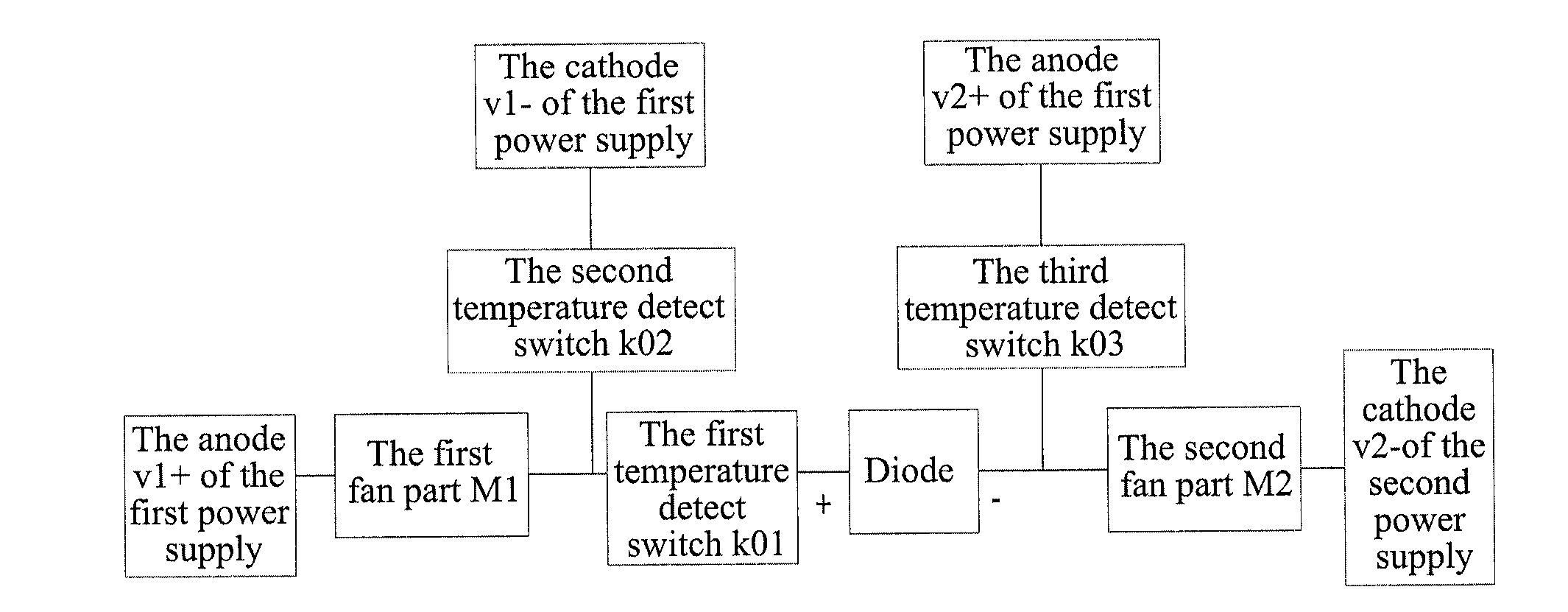
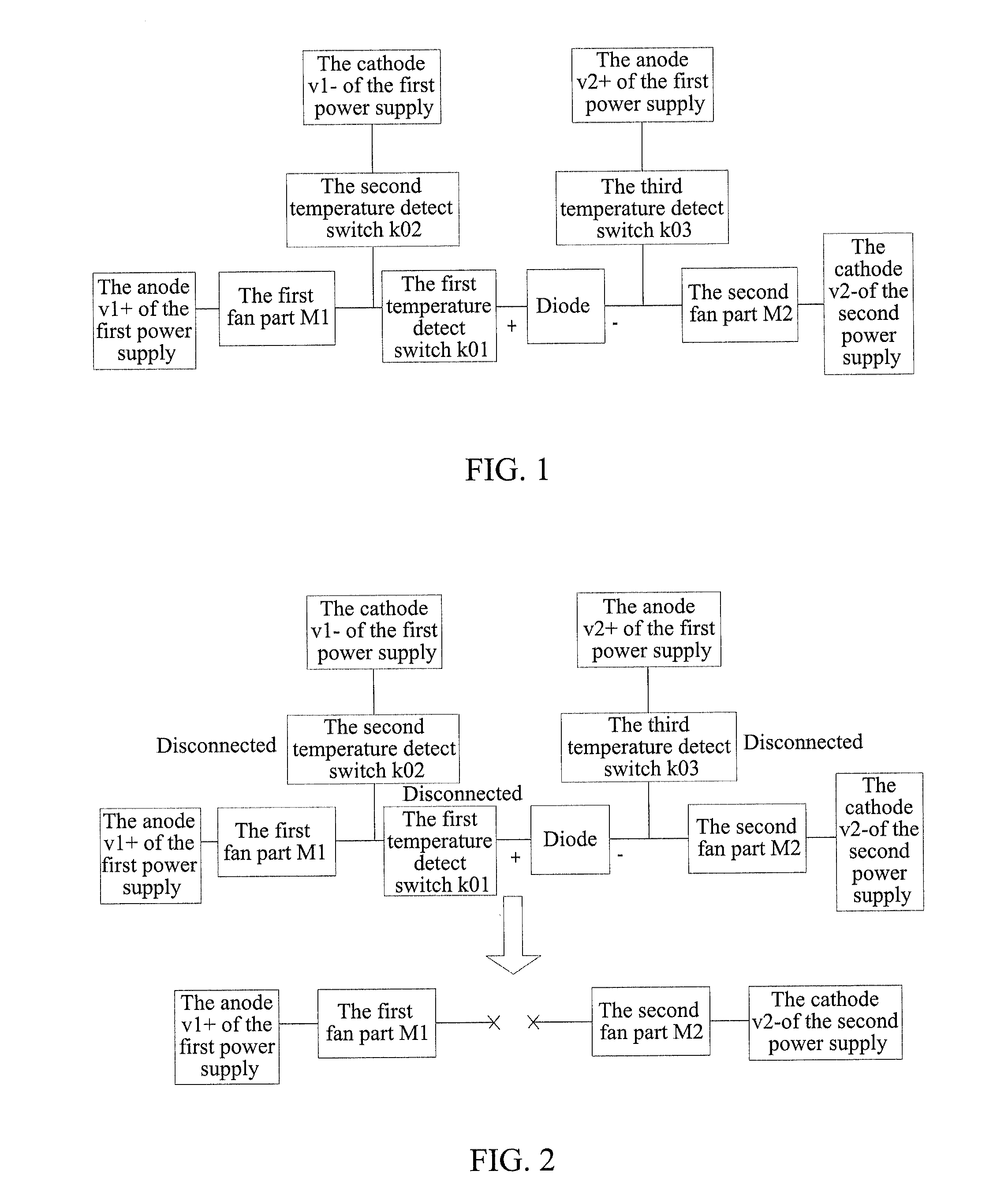
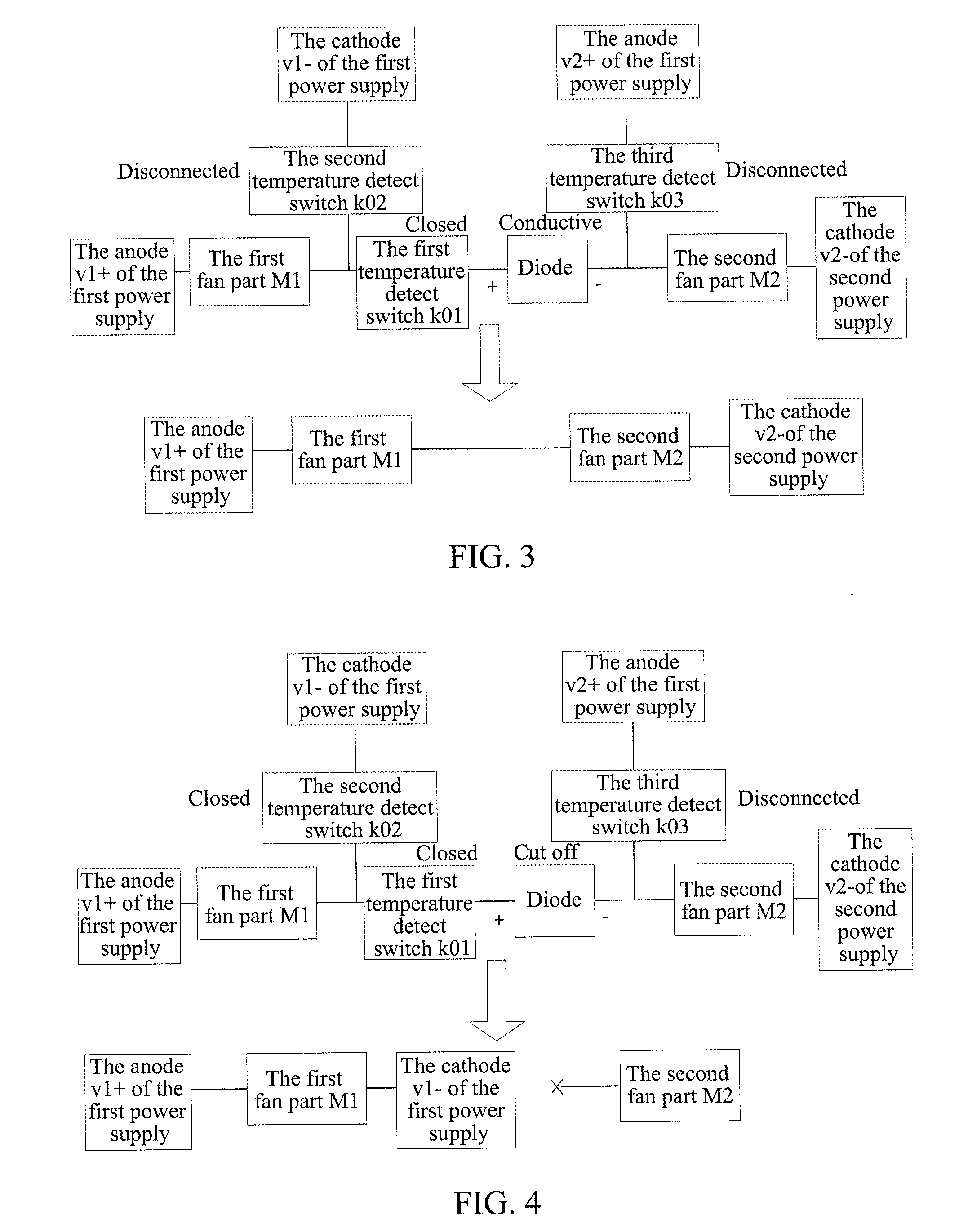
A fan type temperature control method and device are provided. The device includes a fan unit including a plurality of fans and cooling an apparatus to be cooled, power supplies (v1,v2) supplying power for the fans in the fan unit, and a fan control unit which controls the fans as follows: when temperature t of the apparatus is lower than critical temperature t1 of a first temperature detect switch (k01), all fans stop; when t is higher than t1 and lower than critical temperature t2 of a second temperature detect switch (k02), all fans rotate at half speed; when t is higher than t2 while lower than critical temperature t3 of a third temperature detect switch (k03), a first fan part (M1) rotates at full speed and a second fan part (M2) stops; when t is higher than t3, all fans rotate at full speed.

Description

TECHNICAL FIELD[0001]The present invention relates to a forced air-cooling thermal design scheme, and more especially, to a fan type temperature control method and device.BACKGROUND OF THE RELATED ART[0002]With the increasingly high integration level of the systems, the widespread use of the large power devices, the requirements of miniaturization of the product volume, more extensive application environments, and the continuous improvement of the system working speed, thermal management design has become an indispensable means to improve system reliability.[0003]In the thermal design, considering the heat flux density of the device, the volumetric power density and temperature rise, the common cooling methods are natural cooling and forced air cooling. When the heat flux of the electronic device is more than 0.08 w / cm2 and the volumetric power density is over 0.18 w / cm3, the natural cooling alone cannot completely solve the cooling problem, and many systems require additional dynam...

Claims


Application Information

Patent Timeline
Patent Type & Authority Applications(United States)
IPC IPC(8): F24F7/007
CPCG05D23/1912H05K7/20209G06F1/206G06F1/20
Inventor MENG, YANNIRONG, HUILIU, MINGMINGZHOU, BAOHANGWEI, SHUWANGTENG, LINGQIAO
Owner ZTE CORP
Learn More