Shock energy absorber

Inactive Publication Date: 2012-07-26
FOSTER-MILLER
View PDF18 Cites 22 Cited by
  • Summary
  • Abstract
  • Description
  • Claims
  • Application Information

AI Technical Summary

Benefits of technology

[0004]This disclosure provides a new concept for a compact shock energy absorber system which can be effectively used for shock mitigation. On the basis of a series of laboratory tests and a prototype test performed by the inventors, it is concluded that a significant amount of energy can be absorbed in an impact, explosive bl

Problems solved by technology

For use in crash energy management system related to vehicular crashworthiness and occupant

Method used


Image

  • Shock energy absorber
  • Shock energy absorber
  • Shock energy absorber

Examples


Embodiment Construction

[0041]Aside from the preferred embodiment or embodiments disclosed below, this invention is capable of other embodiments and of being practiced or being carried out in various ways. Thus, it is to be understood that the invention is not limited in its application to the details of construction and the arrangements of components set forth in the following description or illustrated in the drawings. If only one embodiment is described herein, the claims hereof are not to be limited to that embodiment. Moreover, the claims hereof are not to be read restrictively unless there is clear and convincing evidence manifesting a certain exclusion, restriction, or disclaimer.

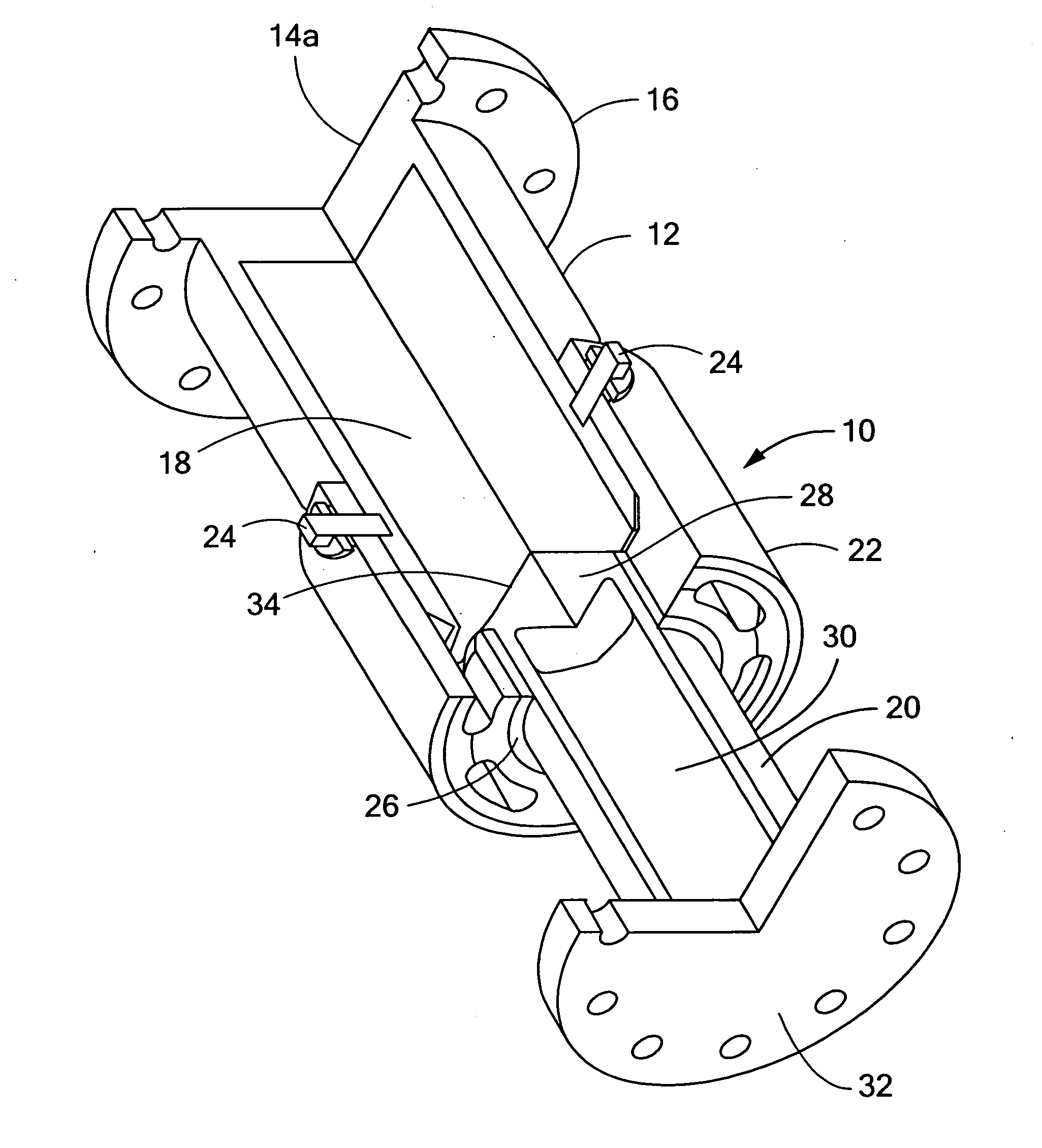
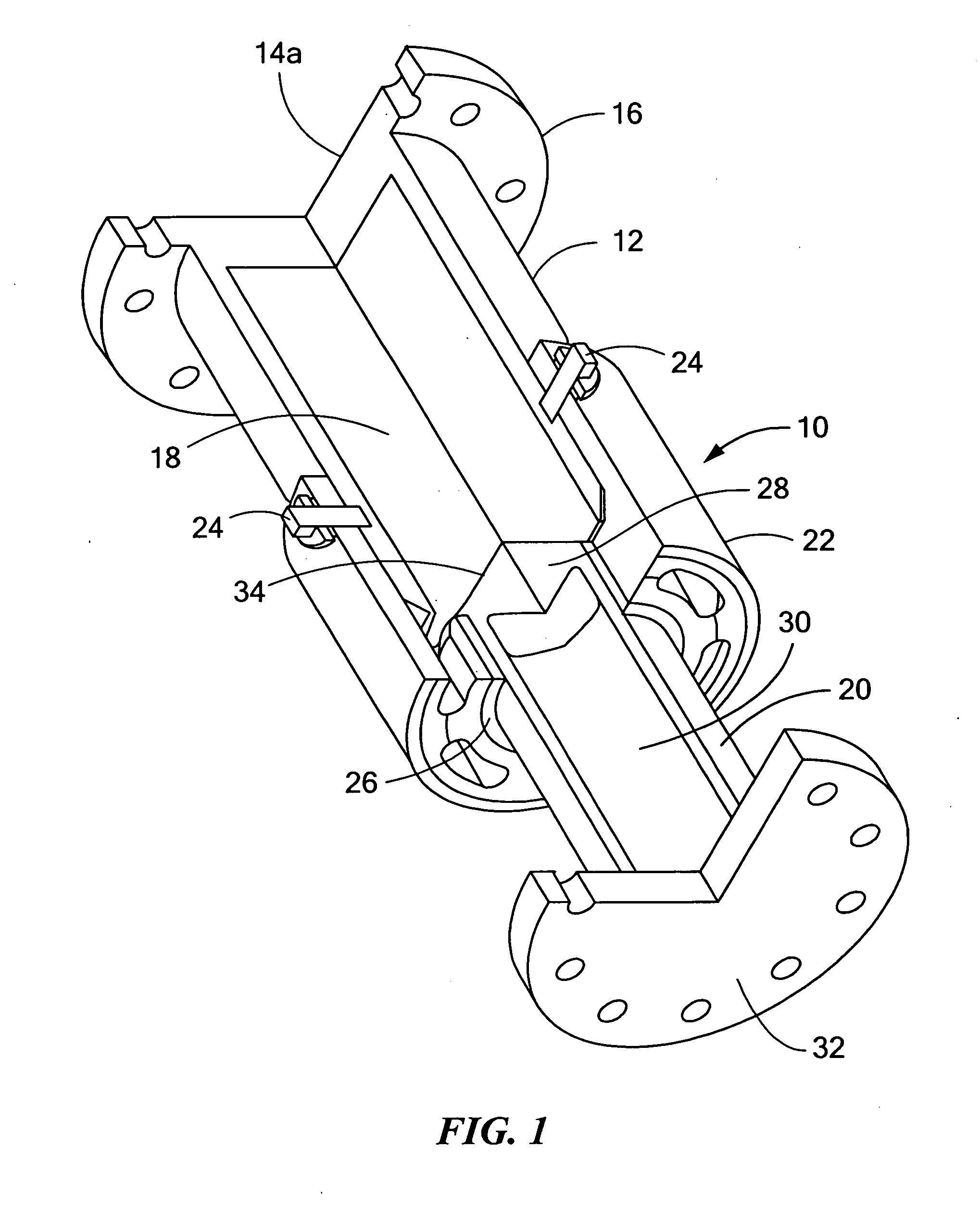
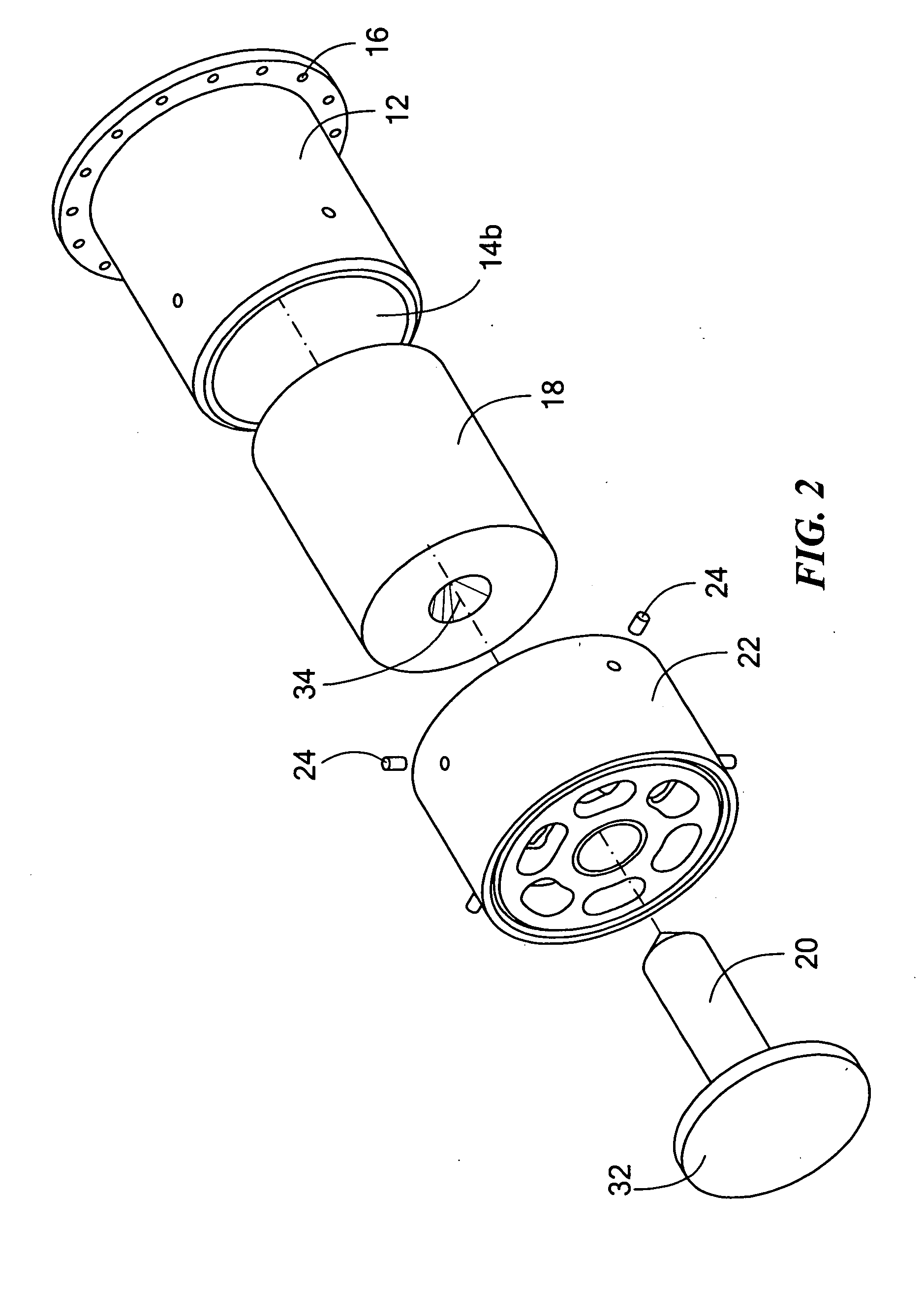
[0042]A novel compact high energy shock absorber can preferably be made of very few machined parts. The major components in one example are shown in FIGS. 1-2. Shock energy absorber 10 includes vessel 12, in this particular example, a cylinder with closed end 14a and open end 14b. In this example, flange 16 is included at c...


PUM


Abstract

A shock absorber includes damping material in a solid state and which transitions from a solid to a viscous fluid state when stressed and a plunger device including a depending blade positioned in or adjacent the damping material to be driven into the damping material when impacted transitioning the damping material to a viscous fluid state absorbing the impact.

Description

RELATED APPLICATIONS[0001]This application is a continuation-in-part application of U.S. patent application Ser. No. 12 / 925,354 filed Oct. 19, 2010 which claims the benefit of and priority to U.S. Provisional Application Ser. No. 61 / 281,314 filed on Nov. 16, 2009, each of which is incorporated herein by reference, under 35 U.S.C. §§119, 120, 363, 365, and 37 C.F.R. §1.55 and §1.78.FIELD OF THE INVENTION[0002]The subject invention relates to energy absorption.BACKGROUND OF THE INVENTION[0003]Generally, shock absorbers are oleo type or oleo-pneumatic type in which the oil is forced to pass through a plurality of orifices within a cylinder-piston arrangement under increasing pressure caused by the impacting force and thereby damping out the relative motion between the cylinder and piston as well as attenuating the transmitted force magnitude. Alternative shock absorbers may use a thin-walled hollow cylinder which crumples and absorbs energy under impact condition. The physical dimensio...

Claims


Application Information

Patent Timeline
IPC IPC(8): F41H7/02F16F9/30
CPCF16F9/30B61G11/12F16F7/003
Inventor PARIDA, BASANT K.DANA, NORMANZAOUK, ABDULLATIF K.
Owner FOSTER-MILLER
Why Eureka
Try Eureka