Power unit for electric vehicle

a technology for electric vehicles and power units, which is applied in the direction of motor/generator/converter stoppers, dynamo-electric converter control, instruments, etc., can solve the problems of increasing the switching loss of the inverter of the motor driving the vehicle, and achieve the desired engine performance, enhance the driving efficiency of the inverter, and prevent the driving voltage of the electric motor

Active Publication Date: 2012-07-26
HONDA MOTOR CO LTD
View PDF8 Cites 12 Cited by
  • Summary
  • Abstract
  • Description
  • Claims
  • Application Information

AI Technical Summary

Benefits of technology

[0004]Incidentally, according to the power source system based on the conventional technology described above, when the power source system is mounted on a large vehicle, for example, and the power output of the fuel cell stack and the electric storage device is increased, the connection in series voltage increases as well. As a result, there is an increase in the switching loss of the inverter of the motor driving the vehicle. Thus, when the vehicle is traveling in a high-torque cruising mode, during a starting of the vehicle on a hill, for example, an output restriction might occur in order to prevent the inverter from overheating.
[0005]The present invention is made according to such considerations. An object of the present invention is to provide a power unit for an electric vehicle which can maintain a predetermined output while restraining a loss in a high-voltage system.
[0015]In these ways, when the load of the electric motor is large, a desired engine performance may be obtained by increasing the drive voltage of the electric motor. When the load of the electric motor is small, the drive voltage of the electric motor is prevented from becoming exceedingly large. Therefore, it is possible to enhance the driving efficiency of the inverter which drives and controls the electric motor. It is also possible to enhance the driving efficiency of the electric motor.
[0016]Therefore, even when the vehicle is traveling in a high-torque cruising mode, during a starting of the vehicle on a hill, for example, it is possible to prevent an increase in the switching loss of the inverter driving and controlling the electric motor. It is also possible to prevent overheating. Thus, it is possible to prevent an output restriction against the cruising control from occurring.
[0018]As a result, it is possible to switch the connection between the first power source and the second power source with respect to the electric motor between a connection in parallel and a connection in series according to the magnitude of the load of the electric motor in a condition in which the electric power supply with respect to the electric motor is maintained. For example, even during an AER (All Electric Range) travel, when the vehicle is run only with electric power supplied by the battery without using power from an internal combustion, the cruise control may be maintained at least by the electric power supplied by the first power source.
[0019]According to a power unit for an electric vehicle based on (3) above, the first power source and the second power source are connected in series in the second connection condition. In this second connection condition, the DC-DC converter performs a switching operation. As a result, it is possible to adjust a power output ratio between the first battery source and the second battery source.

Problems solved by technology

As a result, there is an increase in the switching loss of the inverter of the motor driving the vehicle.

Method used


Image

  • Power unit for electric vehicle
  • Power unit for electric vehicle
  • Power unit for electric vehicle

Examples


Embodiment Construction

[0042]Hereunder, a power unit for an electric vehicle according to an embodiment of the present invention is described with reference to the attached diagrams.

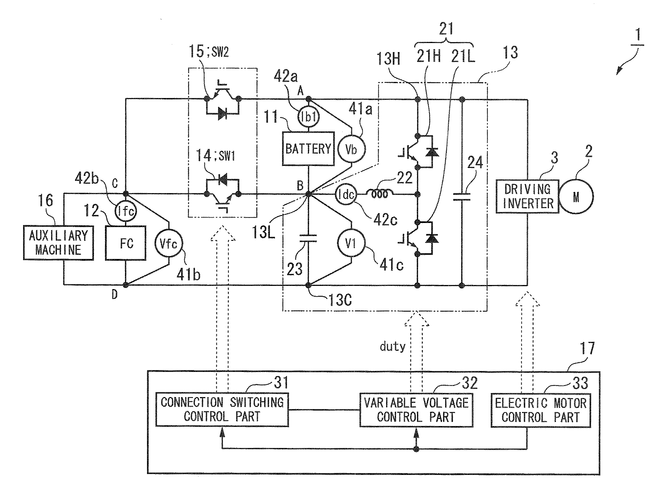
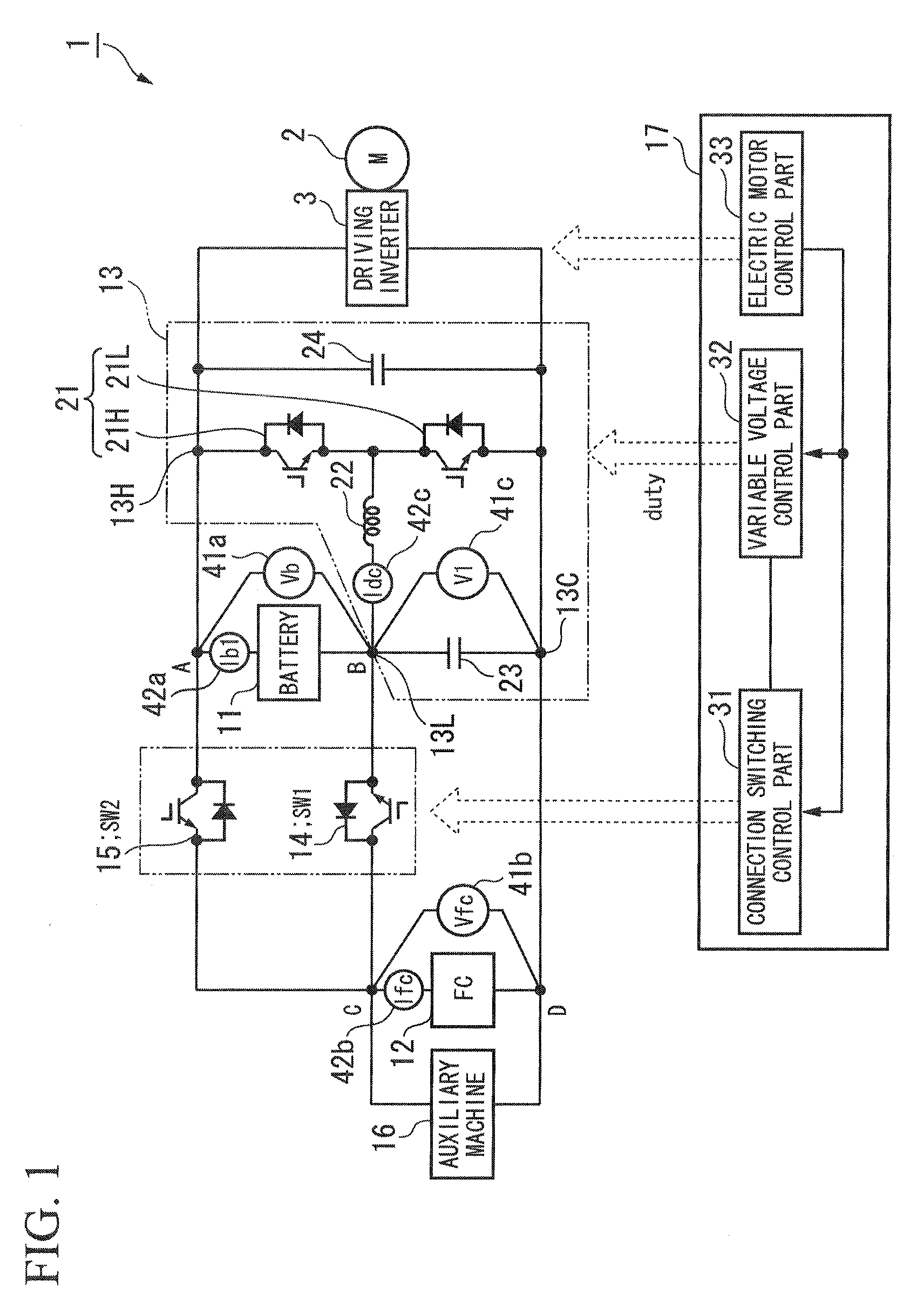
[0043]As shown in FIG. 1, for example, the power unit 1 for the electric vehicle according to the above embodiment comprises a power source supplying electric power to a driving inverter 3 for driving and controlling a electric motor (M) 2 generating a cruise driving force of the electric vehicle.

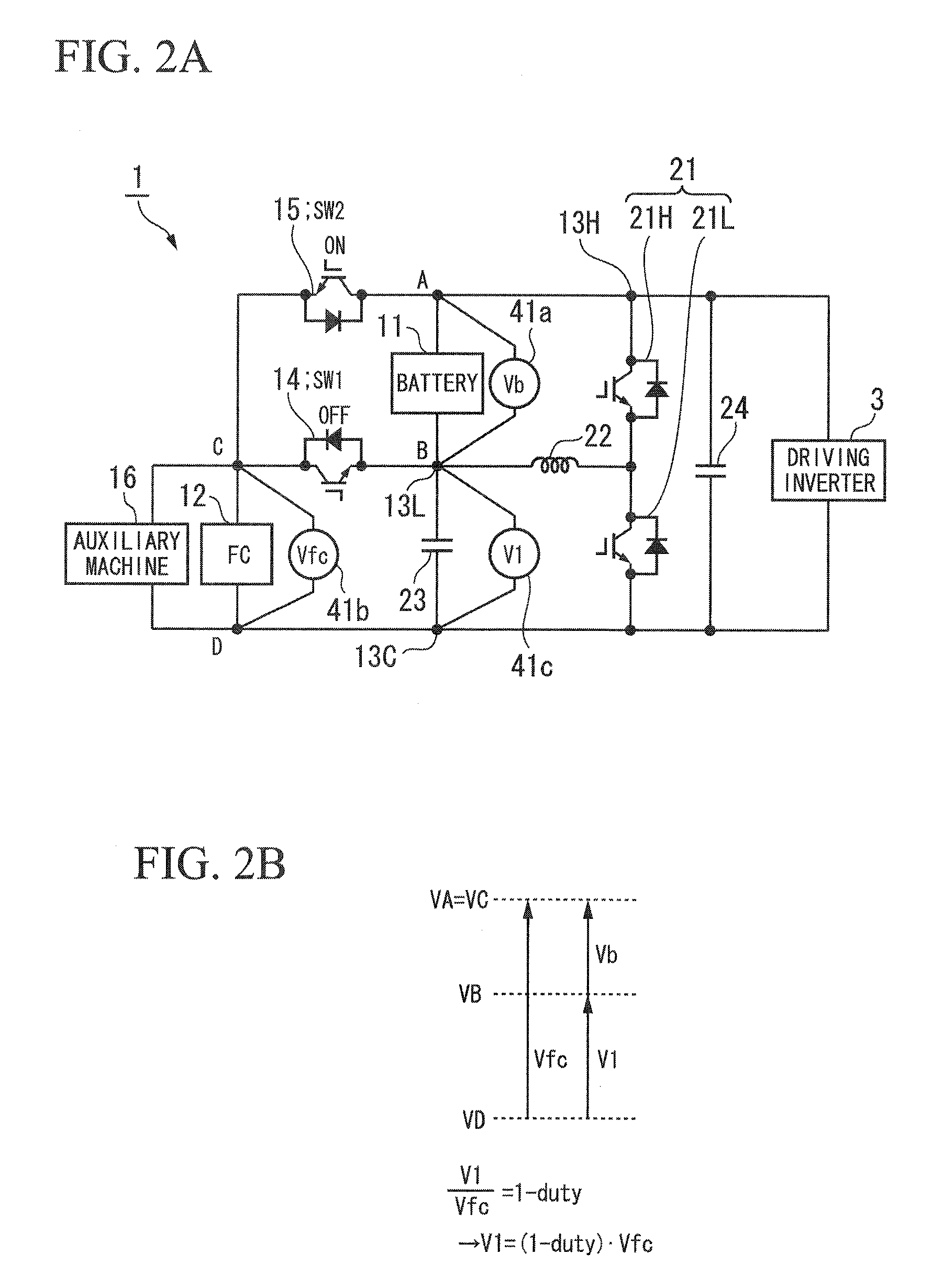
[0044]The power unit 1 for the electric vehicle comprises a first node A, a second node B, a third node C, a fourth node D, a battery 11, a fuel cell stack (FC) 12, DC-DC converter 13, a first switch (SW1) 14, a second switch (SW2) 15, an auxiliary machine 16, and a control device 17.

[0045]The driving inverter 3 is connected to the first node A and the fourth node D in parallel.

[0046]The battery 11 is connected between the first node A and the second node B.

[0047]The fuel cell stack (FC) 12 is connected between the third node C and th...


PUM


Abstract

A power unit for an electric vehicle includes: a first power source connected between a first node and a second node; a first switch connected between the second node and a third node; a second power source connected between the third node and a fourth node; a second switch connected between the first node and the third node; and a DC-DC converter, wherein the DC-DC converter adjusts an electric potential of the first node by changing an electric potential of the second node by making the first node connectable to the third node, or, by making the second node connectable to the third node; an output electric power obtained from between the first node and the fourth node is supplied to an electric motor; and the first power source or the second power source is a fuel cell stack and an another is a secondary battery.

Description

TECHNICAL FIELD[0001]The present invention relates to a power unit for an electric vehicle.[0002]Priority is claimed on Japanese Patent Application No. 2011-010585, filed Jan. 21, 2011, the content of which is incorporated herein by reference.BACKGROUND ART[0003]Conventionally, a power source system is known which includes a single DC-DC converter for a battery circuit. This battery circuit is configured so that a fuel cell stack and an electric storage device are connected in series. According to the above conventional power source system, a switching is performed between a plurality of operation modes by adjusting the electric power supply ratio between the fuel cell stack and the electric storage device by altering a switching duty of the DC-DC converter. (See, for example, Japanese Unexamined Patent Application, First Publication No. 2010-104165.)DISCLOSURE OF INVENTION[0004]Incidentally, according to the power source system based on the conventional technology described above, ...

Claims


Application Information

Patent Timeline
Patent Type & Authority Applications(United States)
IPC IPC(8): B60L1/00
CPCB60L1/003Y02T10/7275B60L3/0061B60L11/1803B60L11/1887B60L15/2063B60L2210/10B60L2240/36B60L2240/421B60L2240/423B60L2240/427B60L2240/529B60L2240/547B60L2240/549B60L7/18Y02T10/7216Y02T90/34Y02T10/642B60L3/003B60L50/51B60L58/40Y02T10/64Y02T10/72Y02T10/70Y02T90/40
Inventor SONE, TOSHIHIRO
Owner HONDA MOTOR CO LTD
Why Eureka
Try Eureka