Lighting system, electronic device for a lighting system and method for operating the electronic device

a technology of electronic devices and lighting systems, applied in lighting apparatus, electroluminescent light sources, light sources, etc., can solve the problems of flickering leds and reduced luminance, and achieve the effect of reducing the noise sensitivity of output signals and reducing the sensitivity of electronic devices

Active Publication Date: 2012-07-26
TEXAS INSTR INC
View PDF4 Cites 47 Cited by
  • Summary
  • Abstract
  • Description
  • Claims
  • Application Information

AI Technical Summary

Benefits of technology

[0015]Further, the input voltage that is coupled to the non-inverting input of the error amplifier as a reference voltage is filtered by a low pass filter that removes noise and spikes from the reference signal. The input voltage is further limited to a predetermined maximum voltage, a maximum voltage of the error amplifier.
[0016]According to an embodiment of the invention, the output terminal of the error amplifier is coupled to a load which decreases the noise sensitivity of the output signal of the error amplifier. According to another embodiment, a DC path is present between the inverting input of the error amplifier that is coupled to the reference voltage and the output of the error amplifier. This DC path further decreases the sensitivity of the electronic device with respect to noise.

Problems solved by technology

This leads to flickering of the LEDs but not to a reduced luminance as desired by the user that operates the TRIAC dimmer exactly for that purpose.

Method used


Image

  • Lighting system, electronic device for a lighting system and method for operating the electronic device
  • Lighting system, electronic device for a lighting system and method for operating the electronic device
  • Lighting system, electronic device for a lighting system and method for operating the electronic device

Examples


Embodiment Construction

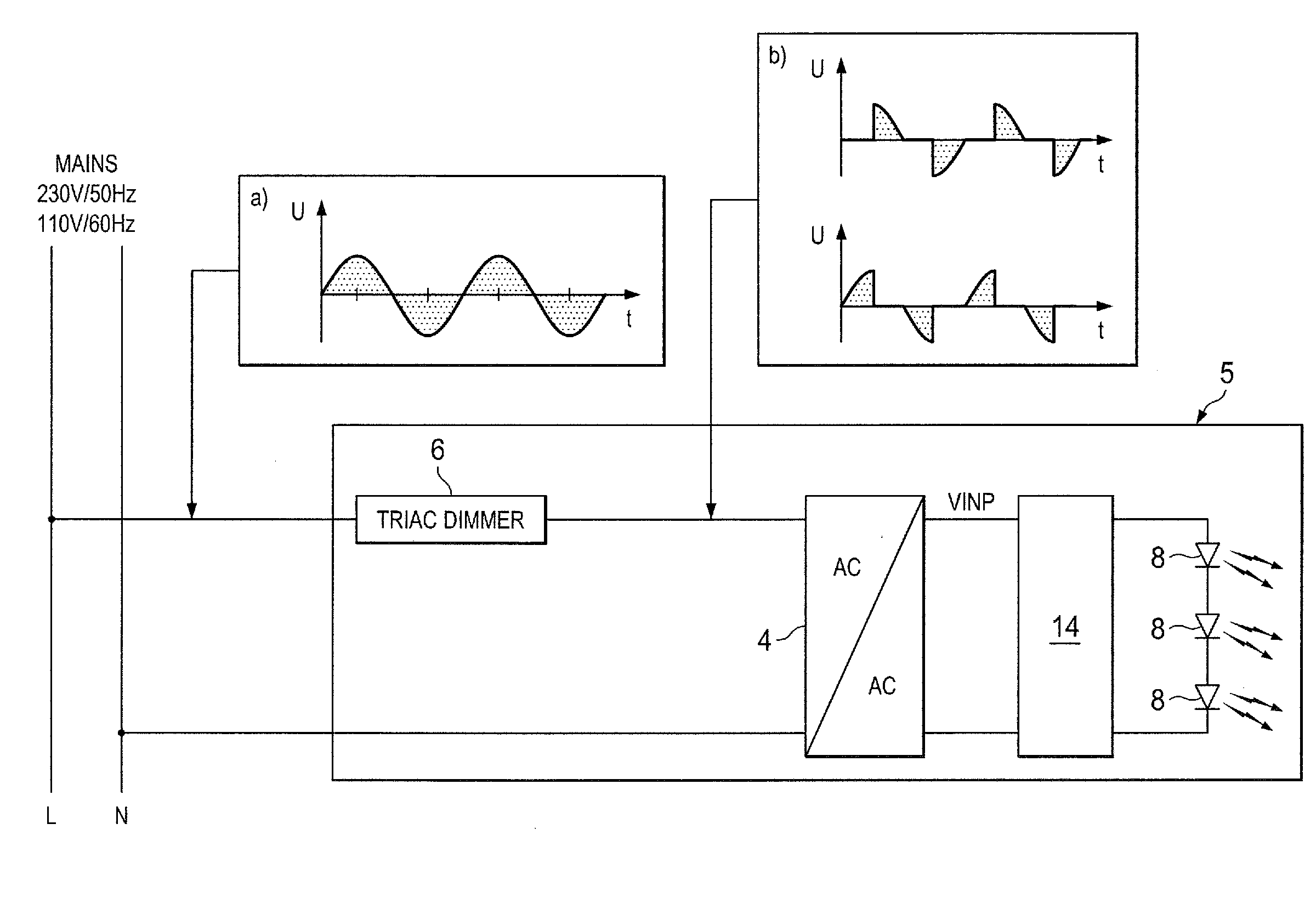
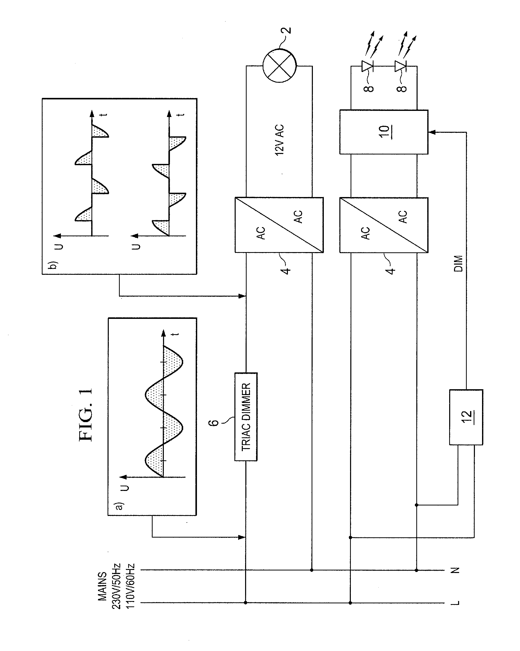
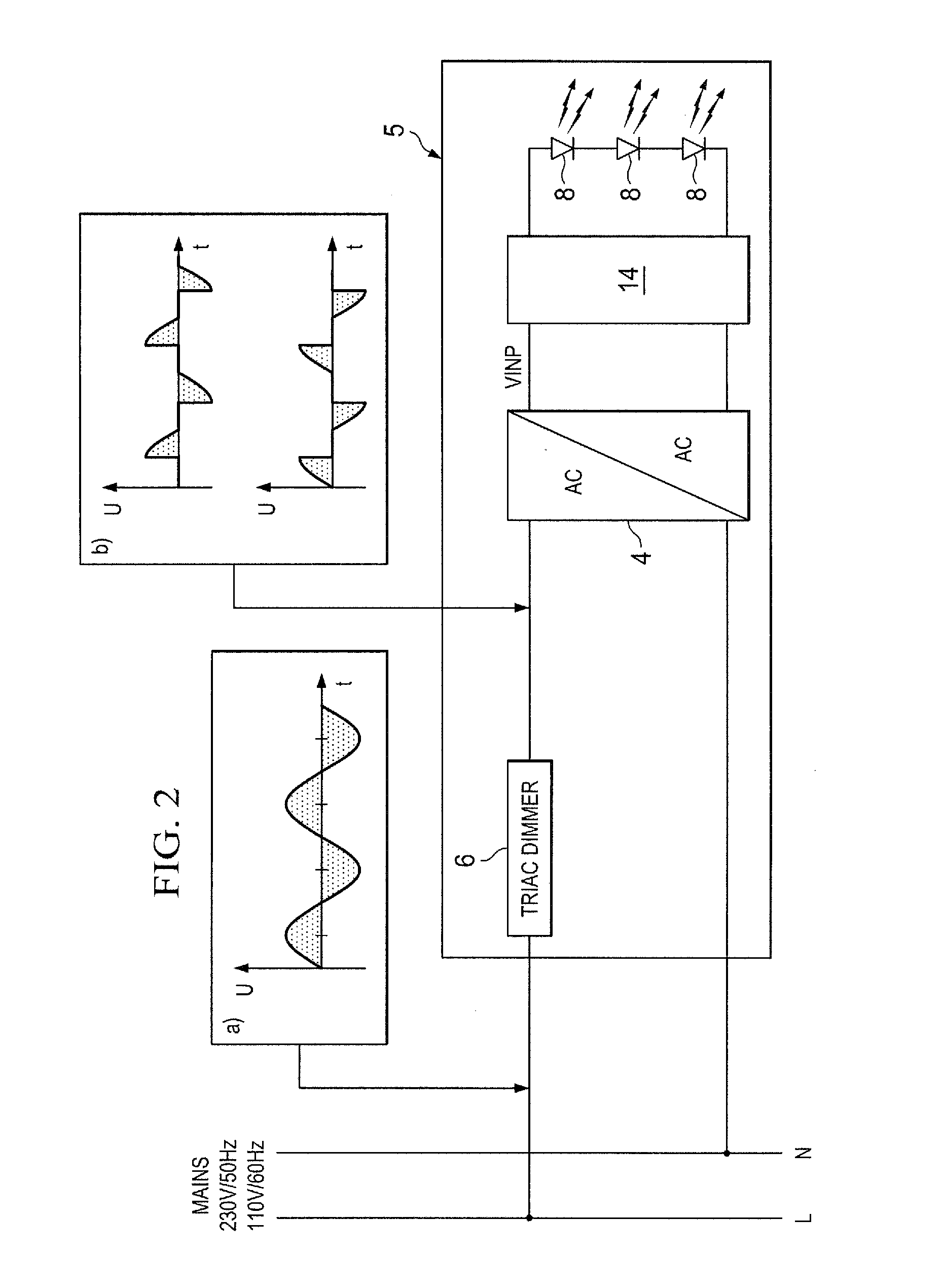
[0027]FIG. 2 is an LED based lighting system 5 according to an embodiment of the invention. A TRIAC dimmer 6 cutting the leading or the trailing edge of a sinusoidal primary supply voltage of 230 V at 50 kHz in Europe or 110 V at 60 Hz in the U.S. is coupled to the primary side of an AC / AC transformer 4. The transformer 4 may be a classical iron core or an electronic transformer. The cut output voltage of the TRIAC dimmer 6 is schematically illustrated by the insets a) and b) in FIG. 2. At the secondary side of the transformer 4, an electronic device 14 according to an embodiment of the invention receives the phase cut voltage as an input voltage and provides a supply voltage to the LED chain 8.

[0028]FIG. 3 is a detailed view of the electronic device 14. A phase cut input voltage VINP is provided to a rectifier comprising diodes D1, D2, D5 and D6. The rectified voltage is smoothed by a low pass filter comprising the inductance L1 of 10 μH, for example, and capacitor C1 of 10 μF, for...


PUM


Abstract

An electronic device for a lighting system, comprising a TRIAC dimmer configured to receive a mains supply voltage and provide a phase cut voltage to the electronic device and having a control loop configured to control a duty cycle of a switched voltage converter that receives the rectified input voltage and provides drive current to a light emitting semiconductor device. The control loop has an error amplifier that is coupled to receive a sense voltage that is indicative of a current through the light emitting semiconductor device, the error amplifier is configured to provide a feedback signal to a pulse width modulation logic configured to control the duty cycle of the switched voltage converter to provide a constant drive current to the light emitting semiconductor device in response to the sense voltage, the error amplifier being coupled to receive a reference voltage that is a function of the input voltage.

Description

CROSS-REFERENCE TO RELATED APPLICATIONS[0001]This patent application claims priority from German Patent Application No. 10 2011 007 990.4, filed Jan. 6, 2011, which is incorporated herein by reference in its entirety.FIELD OF THE INVENTION[0002]The invention relates to a lighting system comprising a TRIAC dimmer, an electronic device for the lighting system and further to a method for operating the electronic device.BACKGROUND OF THE INVENTION[0003]In a conventional halogen lighting system as schematically and exemplarily illustrated in the upper part of FIG. 1, a halogen bulb 2 or a plurality of halogen bulbs is / are connected via an AC / AC transformer 4 to a mains supply having a voltage of typically 230 V at 50 Hz in Europe and 110 V at 60 Hz in the U.S. If a classical iron core transformer 4 is used, the turns ratio is adapted to the mains voltage so as to provide 12 V AC to the halogen bulb 2. Since classical transformers are large and heavy due to the iron core and copper windin...

Claims


Application Information

Patent Timeline
Patent Type & Authority Applications(United States)
IPC IPC(8): H05B37/02H05B44/00
CPCH05B33/0815H05B45/375H05B45/3725H05B45/38
Inventor ULMANN, MATTHIAS U.MARJANOVIC, MILAN
Owner TEXAS INSTR INC
Why Eureka
Try Eureka