Common detector for combined raman spectroscopy-optical coherence tomography

a technology of optical coherence tomography and combined raman spectroscopy, which is applied in the direction of optical radiation measurement, diagnostics using spectroscopy, interferometric spectrometry, etc., can solve the problems of insufficient instrumentation, inability to rapidly image over a large spatial area, and inability to meet the needs of the art, so as to reduce the complexity of instrumentation, the effect of cost and siz

Active Publication Date: 2012-07-26
ACADEMISCH MEDISCH CENT BIJ DE UNIV VAN +1
View PDF1 Cites 48 Cited by
  • Summary
  • Abstract
  • Description
  • Claims
  • Application Information

AI Technical Summary

Benefits of technology

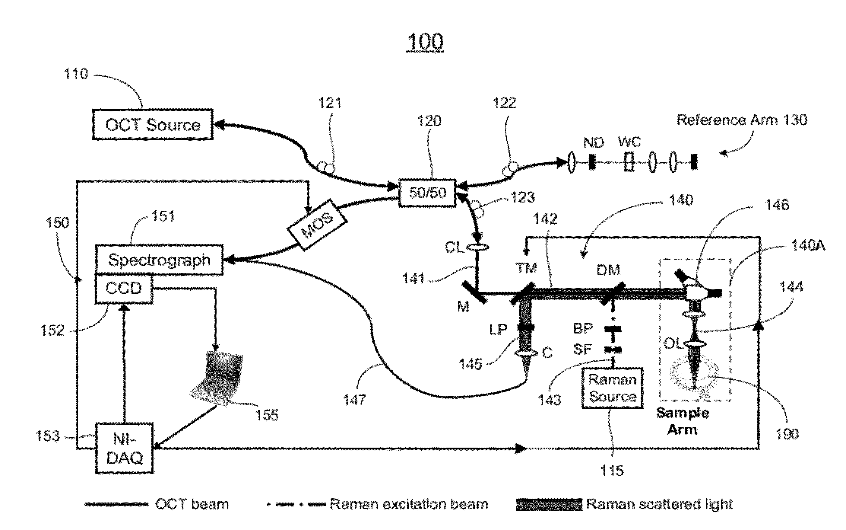
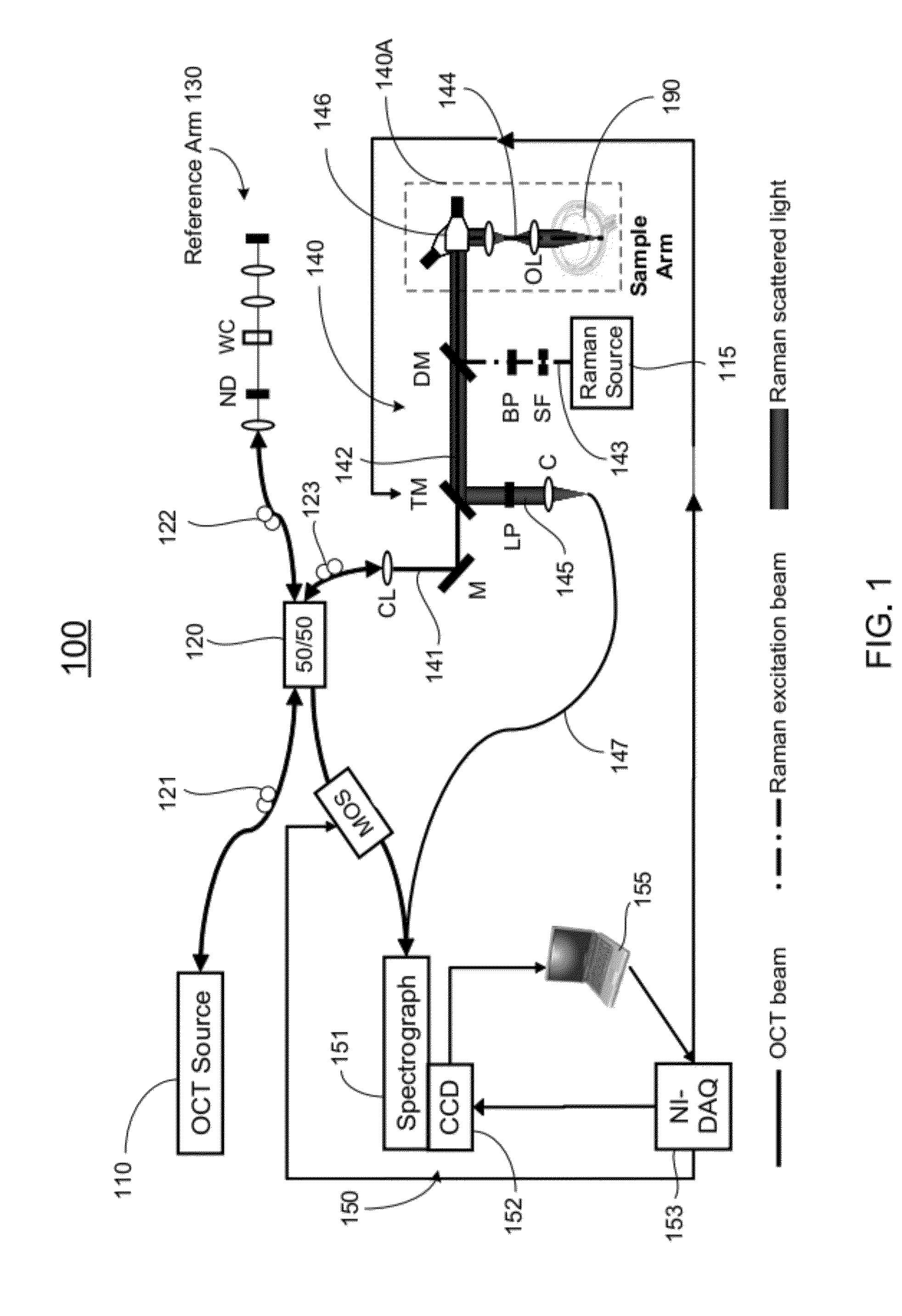
[0007]One of the objectives of the invention is to provide a combined RS and OCT system with a single detector arm for both the RS and OCT, which allows the use of a single spectrometer to detect both modalities. The advantage of a common detector arm is that it significantly reduces the instrumentational complexity, cost, and size from previously reported RS-OCT systems.

Problems solved by technology

This limitation results from the fact that the OCT images are simply maps of reflectivity and do not directly reveal the molecular composition of the sample.
In contrast to the OCT, the primary limitation of the RS is that the weak nature of in-elastic scattering precludes rapid spectral imaging over a large spatial area.
The drawback, however, is that such configurations require extensive instrumentation that may not be necessary if it are possible to further integrate the two modalities.
The primary challenges in the design of a common-detector RS-OCT system are selection of the appropriate light sources, spectrograph design and selection of appropriate detector architecture.
Therefore, a heretofore unaddressed need exists in the art to address the aforementioned deficiencies and inadequacies.

Method used


Image

  • Common detector for combined raman spectroscopy-optical coherence tomography
  • Common detector for combined raman spectroscopy-optical coherence tomography
  • Common detector for combined raman spectroscopy-optical coherence tomography

Examples


Embodiment Construction

[0043]The present disclosure is more particularly described in the following examples that are intended as illustrative only since numerous modifications and variations therein will be apparent to those skilled in the art. Various embodiments of the disclosure are now described in detail. Referring to the drawings, like numbers indicate like components throughout the views. As used in the description herein and throughout the claims that follow, the meaning of “a”, “an”, and “the” includes plural reference unless the context clearly dictates otherwise. Also, as used in the description herein and throughout the claims that follow, the meaning of “in” includes “in” and “on” unless the context clearly dictates otherwise.

[0044]The terms used in this specification generally have their ordinary meanings in the art, within the context of the disclosure, and in the specific context where each term is used. Certain terms that are used to describe the disclosure are discussed below, or elsewh...


PUM


Abstract

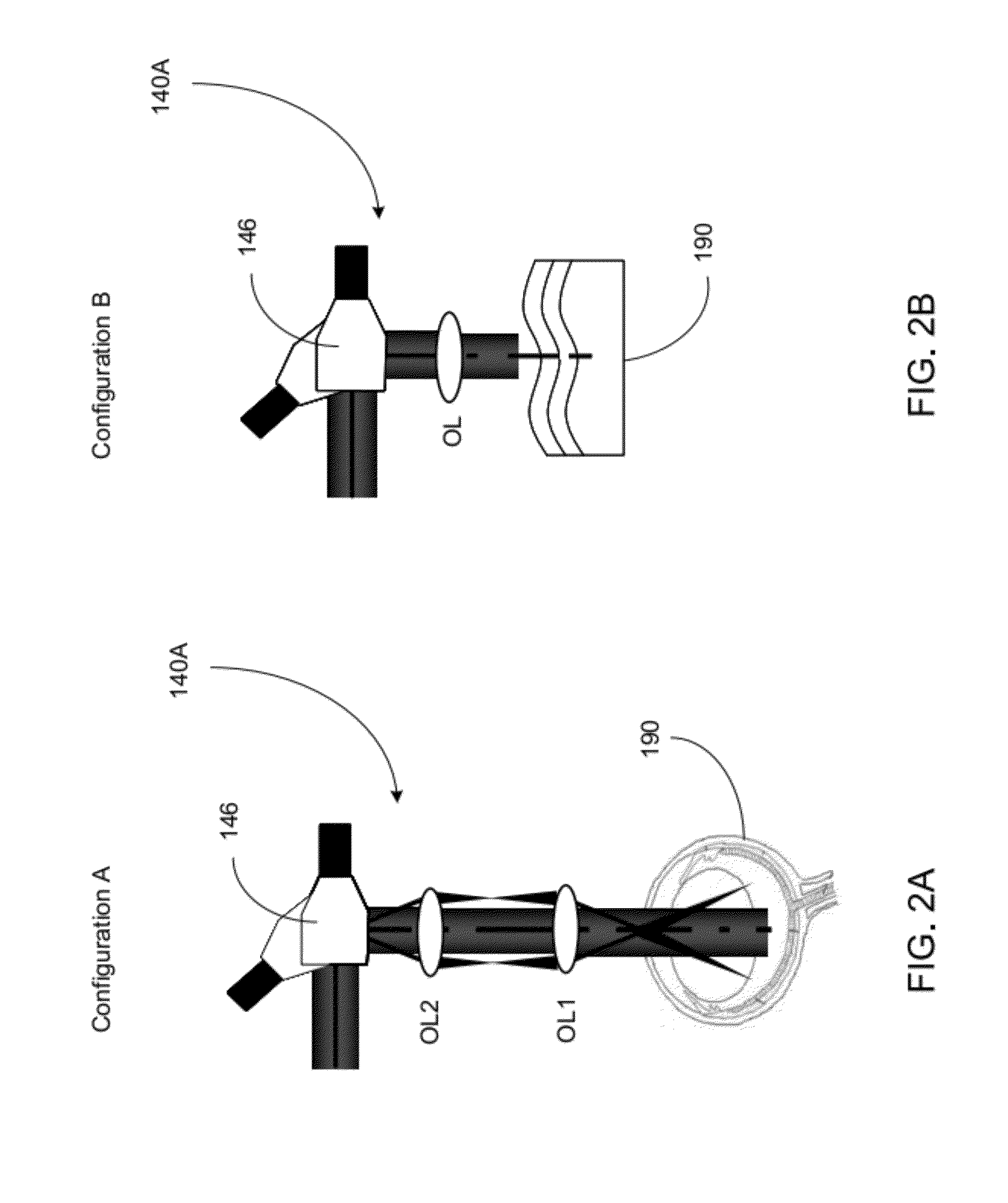
In one aspect of the present invention, an apparatus includes a first light source for generating a broadband light, and a second light source for generating a monochromatic light, a beamsplitter optically coupled to the first light source for receiving the broadband light and splitting the received broadband light into a reference light and a sample light, a reference arm optically coupled to the beamsplitter for receiving the reference light and returning the received reference light into the beamsplitter, and a sample arm optically coupled to the beamsplitter and the second light source for combining the sample light and the monochromatic light, delivering the combined sample and monochromatic light to the target of interest, collecting a backscattering light and a Raman scattering light that are generated from interaction of the sample light and the monochromatic light with the target of interest, respectively, returning the backscattering light into the beamsplitter so as to generate an interference signal between the returned backscattering light and the returned reference light in the beamsplitter, and directing the Raman scattering light in an output optical path, and a single detector optically coupled to the beamsplitter for collecting the interference signal.

Description

STATEMENT OF FEDERALLY-SPONSORED RESEARCH[0001]This invention is made with government support awarded by the National Institutes of Health of the United States under Contract No. R21 CA133477. The government has certain rights to this invention.CROSS-REFERENCE TO RELATED PATENT APPLICATION[0002]Some references, which may include patents, patent applications and various publications, are cited and discussed in the description of this invention. The citation and / or discussion of such references is provided merely to clarify the description of the present invention and is not an admission that any such reference is “prior art” to the invention described herein. All references cited and discussed in this specification are incorporated herein by reference in their entireties and to the same extent as if each reference is individually incorporated by reference. In terms of notation, hereinafter, “[n]” represents the nth reference cited in the reference list. For example, [13] represents t...

Claims


Application Information

Patent Timeline
Patent Type & Authority Applications(United States)
IPC IPC(8): G01J3/44G01B9/02
CPCA61B3/102A61B5/0066A61B5/0075A61B5/442A61B5/443G01J3/44G01B9/02091G01N21/4795G01N21/65G01N2021/1787G01B9/0203G01B9/02044G01J3/453
Inventor PATIL, CHETAN A.MAHADEVAN-JANSEN, ANITAVAN LEEUWEN, ANTONIUS GERARDUS JOHANNES MARIAKALKMAN, JEROEN
Owner ACADEMISCH MEDISCH CENT BIJ DE UNIV VAN
Why Eureka
Try Eureka