
Image processing apparatus, image processing method, image processing program, and storage medium

a technology of image processing apparatus and image processing method, which is applied in the field of image processing apparatus, image processing method, image processing program, and storage medium, can solve the problems of large pixels having noise components, noise components such as jaggies and ringing, and the tendency to generate noise components

Inactive Publication Date: 2012-07-26
PIONEER CORP
View PDF2 Cites 13 Cited by
  • Summary
  • Abstract
  • Description
  • Claims
  • Application Information

AI Technical Summary

Benefits of technology

[0009]In view of the aforementioned problems, it is therefore an object of the present invention to provide an image processing apparatus, an image processing method, an image processing program, and a storage medium capable of effectively suppressing the generation of the noise component and improving image quality more properly.Means for Solving the Subject
[0050]According to the storage medium of the present invention, by making the computer read the image processing program described above, it is possible to make the computer appropriately function as the image processing apparatus of the present invention described above.

Problems solved by technology

However, according to the conventional technologies by the patent document 1 and the like described above, the image enlargement process causes the noise component, such as rough step-like edges which appear in a diagonal line portion and a curved line portion out of the contour of the image, i.e. so-called jaggies, and a false contour which is generated near the contour of the image, i.e. so-called ringing.
Moreover, the sharpening process enhances or hardly reduces the noise component such as the jaggies and the ringing, which is technically problematic.
In particular, the noise component such as the jaggies and the ringing tends to be generated in pixels having a large difference in the pixel value between adjacent pixels, such as around the contour of the image, i.e. around an edge.

Method used


Image

  • Image processing apparatus, image processing method, image processing program, and storage medium
  • Image processing apparatus, image processing method, image processing program, and storage medium
  • Image processing apparatus, image processing method, image processing program, and storage medium

Examples


first embodiment

(Entire Configuration)

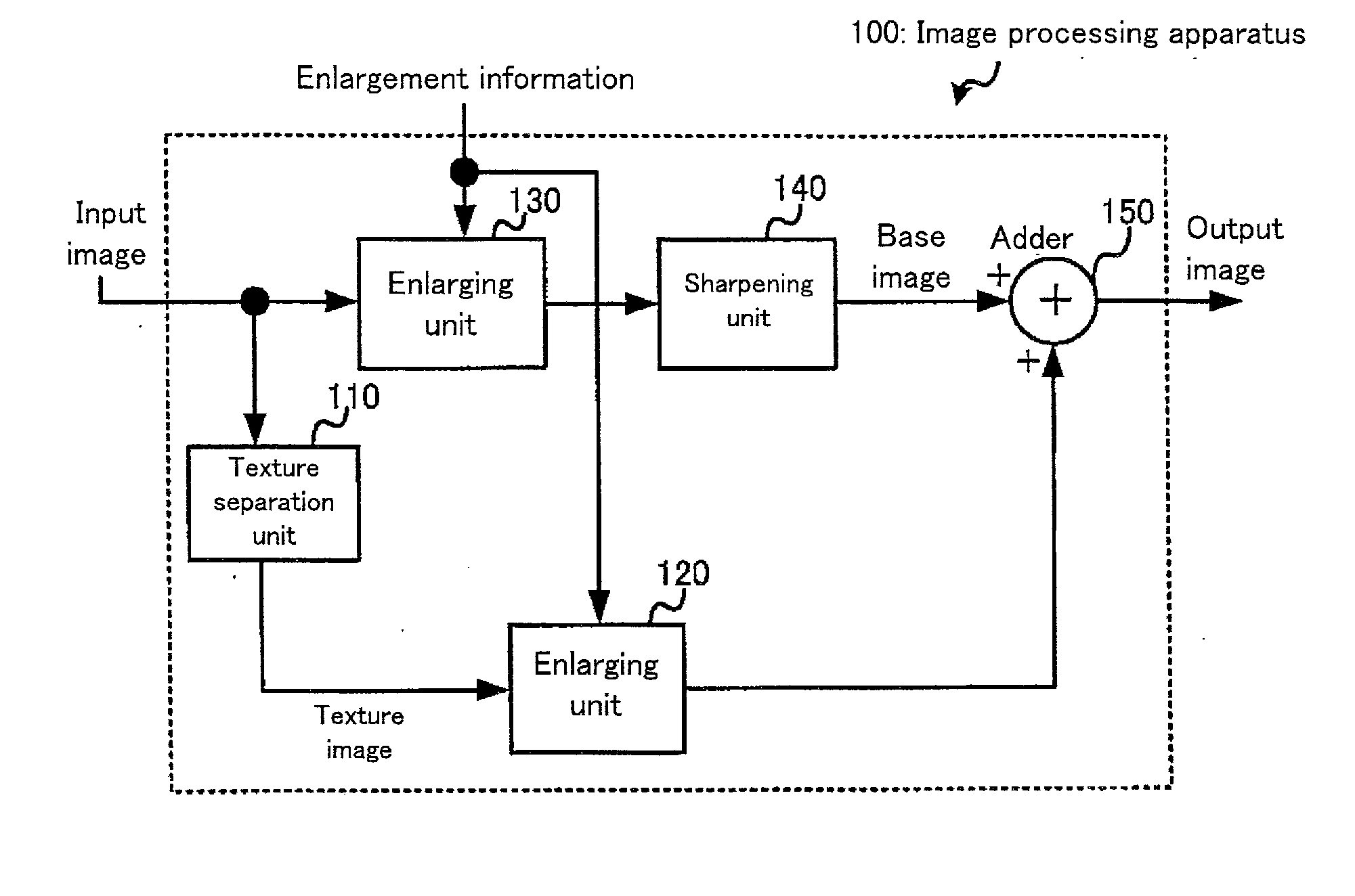
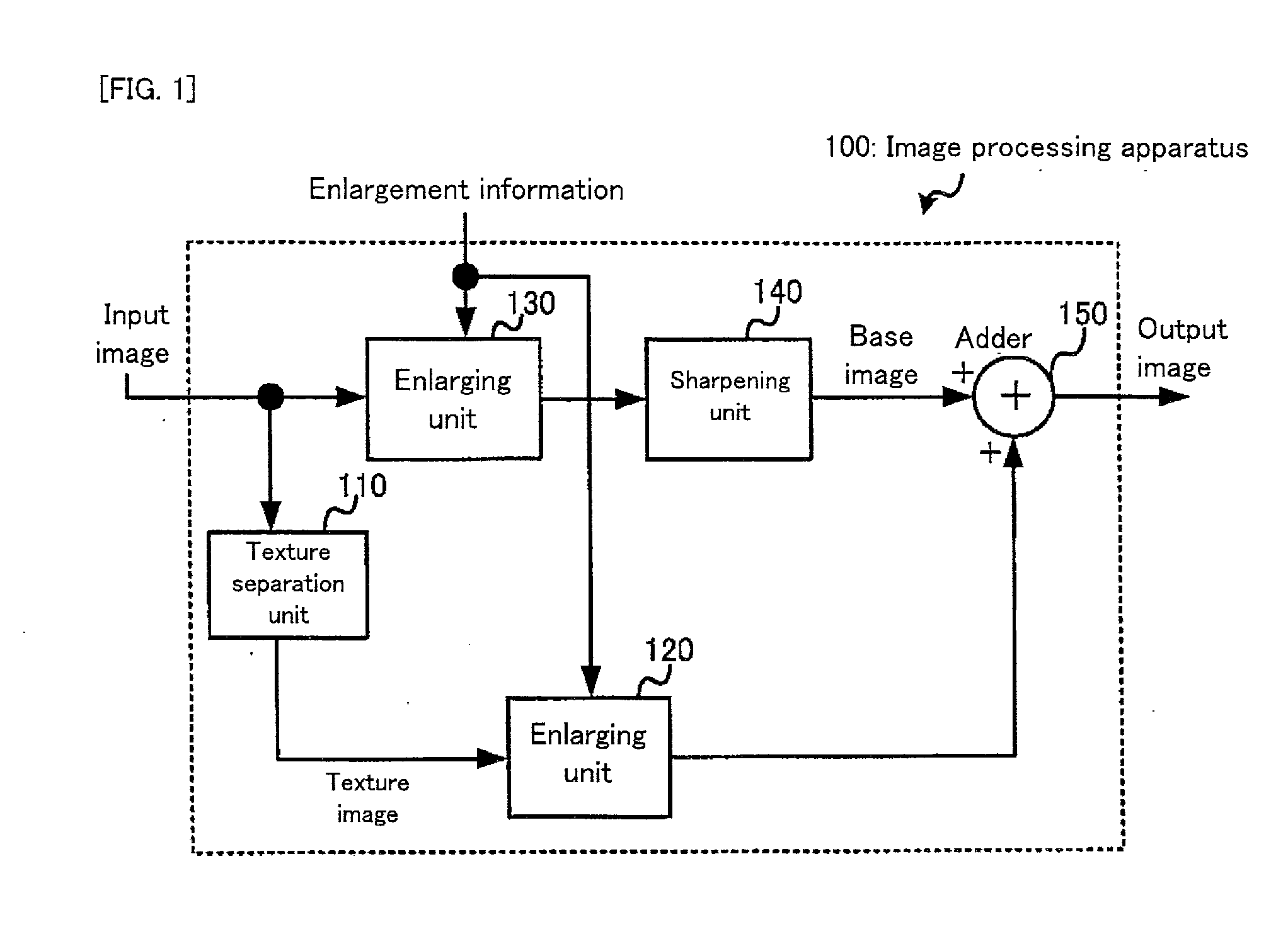
[0063]Firstly, a first embodiment of the present invention will be explained. FIG. 1 is a block diagram showing the entire configuration of an image processing apparatus in the first embodiment.

[0064]As shown in FIG. 1, an image processing apparatus 100 in the first embodiment is provided with a texture separation unit 110, an enlarging unit 120, an enlarging unit 130, a sharpening unit 140, and an adder 150.

[0065]An input image is inputted to each of the texture separation unit 110 and the enlarging unit 130. Incidentally, the input image constitutes one example of the first image of the present invention.

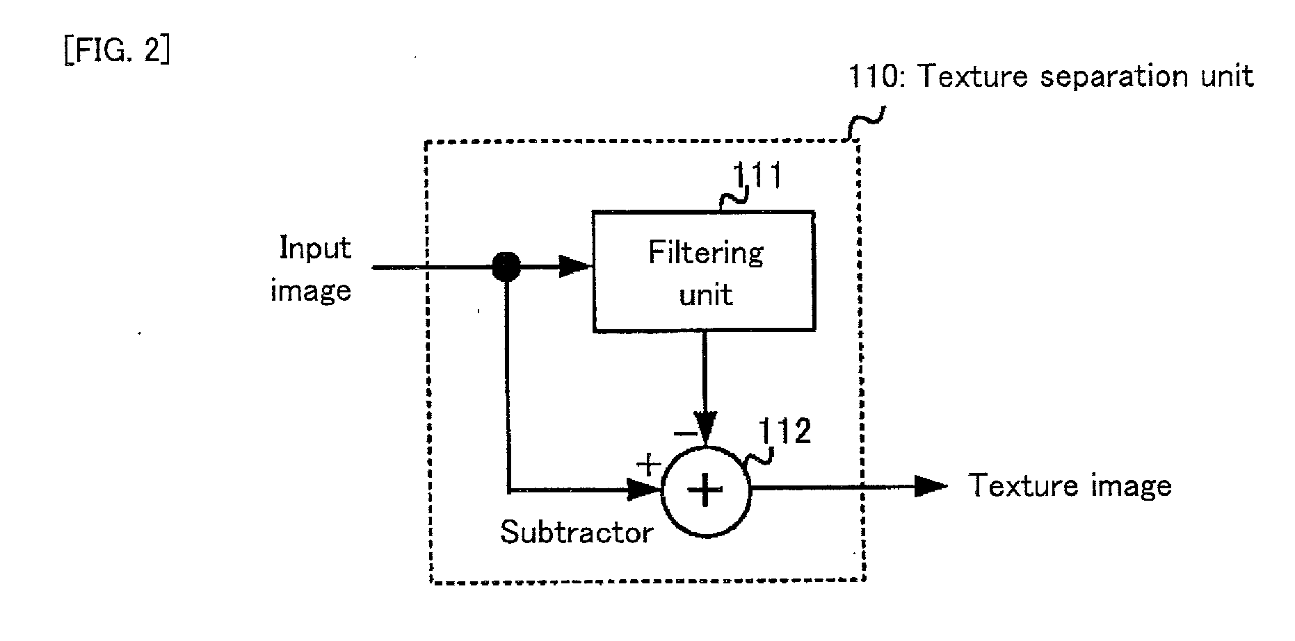
[0066]The texture separation unit 110 separates a texture image from the input image and outputs it. Moreover, enlargement information is inputted to the enlarging unit 120 and the enlarging unit 130. The enlargement information may be information about a magnification for specifying how many times the input image is enlarged. Alternatively, the enlargement i...

second embodiment

(Entire Configuration)

[0104]Next, with reference to FIG. 8 and FIGS. 9, a second embodiment of the present invention will be explained. FIG. 8 is a block diagram showing the entire configuration of an image processing apparatus in the second embodiment. FIGS. 9 are a waveform diagram showing an image that is subject to a gradation correction process in the second embodiment (FIG. 9(a)) and a waveform diagram showing an image that is subject to a gradation correction process in the comparative example (FIG. 9(b)).

[0105]Incidentally, regarding constituents in the second embodiment, substantially the same constituents as those in the first embodiment described above will carry the same reference numerals, and the explanation thereof will be omitted as occasion demands. In addition, in the operations of the second embodiment, an explanation about substantially the same operations as those in the first embodiment described above will be also omitted, as occasion demands.

[0106]As shown in...

third embodiment

(Entire Configuration)

[0121]Next, with reference to FIG. 10 and FIGS. 11, a third embodiment of the present invention will be explained. FIG. 10 is a block diagram showing the entire configuration of an image processing apparatus in the third embodiment. FIGS. 11 are graphs showing a quantitative and qualitative relation between frequency components of an input image and frequency of each frequency component (FIG. 11(a) and FIG. 11(b)).

[0122]Incidentally, regarding constituents in the third embodiment, substantially the same constituents as those in the first embodiment described above will carry the same reference numerals, and the explanation thereof will be omitted as occasion demands. In addition, in the operations of the third embodiment, an explanation about substantially the same operations as those in the first embodiment described above will be also omitted, as occasion demands.

[0123]As shown in FIG. 10, an image processing apparatus 300 in the third embodiment is provided ...


PUM


Abstract

An image processing apparatus (100, 200, 300) is provided with: an obtaining device (110, 130, etc.) for obtaining a first image; an extracting device (110) for extracting a texture image from the obtained first image; a first enlarging device (120) for enlarging the extracted texture image; a second enlarging device (130) for enlarging the obtained first image; a base image obtaining device (140) for obtaining a base image in which a sharpening process is performed on a contour of the enlarged first image to sharpen the contour; and a combining device (150) for combining the enlarged texture image and the obtained base image.

Description

TECHNICAL FIELD [0001]The present invention relates to an image processing apparatus using, for example, a bilateral filter, an image processing method, an image processing program, and a storage medium.BACKGROUND ART[0002]As this type of image processing apparatus, an apparatus for performing a sharpening process after an enlargement process is general. As a general sharpening process, a technology described in a patent document 1 is disclosed. The patent document 1 and the like disclose a technology of making steep rising and falling of the contoured portion of an image without adding any overshoot and undershoot by using a scaling circuit.[0003]Moreover, a non-patent documents 1 and the like disclose a technology about the bilateral filter as a non-linear filter capable of removing a noise component without blurring the contour of the image.[0004]Moreover, a non-patent document 2 and the like disclose a technology about the bilateral filter for making a steep inclination in a spa...

Claims


Application Information

Patent Timeline
Patent Type & Authority Applications(United States)
IPC IPC(8): G06K9/46
CPCG06T5/50G06T2207/20028G06T5/003G06T2207/20221G06T3/40G06T2207/20192G06T5/73
Inventor INABA, MOTOYUKIORIMO, TATSUYAOWADA, HISASHI
Owner PIONEER CORP
Learn More