Radar device and method of calculation of receive power in radar device

a radar device and receive power technology, applied in the direction of measurement devices, using reradiation, instruments, etc., can solve the problems of mispairing, inaccurate calculation of the power of the reflected wave, and inability to accurately calculate the receive power

Active Publication Date: 2012-08-02
FUJITSU GENERAL LTD
View PDF4 Cites 8 Cited by
  • Summary
  • Abstract
  • Description
  • Claims
  • Application Information

AI Technical Summary

Problems solved by technology

The reason is that in the DBF method, other arrival waves are received at the side lobes, so sometimes the power of the reflected waves could not be accurately calculated.
In this regard, when using the Capon method to calculate the power of the reflected waves, if there are a plurality of targets, reflected waves from the plurality of targets end up being received by the antennas and the cross correlation components of the targets are not removed at the time of preprocessing of angle estimation using the spatial average method, so there is the problem that the receive power cannot be accurately calculated.
Therefore, if calculation of the accurate receive power is not possible, the following problems arise.
This is no longer satisfied and the possibility of mispairing occurring rises.
This ends up causing the electronic scan radar device to malfunction.
(2) In composite processing of high resolution processing and a system which requires precision of the power such as an amplitude monopulse, it is not possible to improve the precision of the amplitude monopulse.

Method used


Image

  • Radar device and method of calculation of receive power in radar device
  • Radar device and method of calculation of receive power in radar device
  • Radar device and method of calculation of receive power in radar device

Examples


Embodiment Construction

[0044]Below, the attached drawings will be used to explain in detail the aspects of the present application based on specific embodiments.

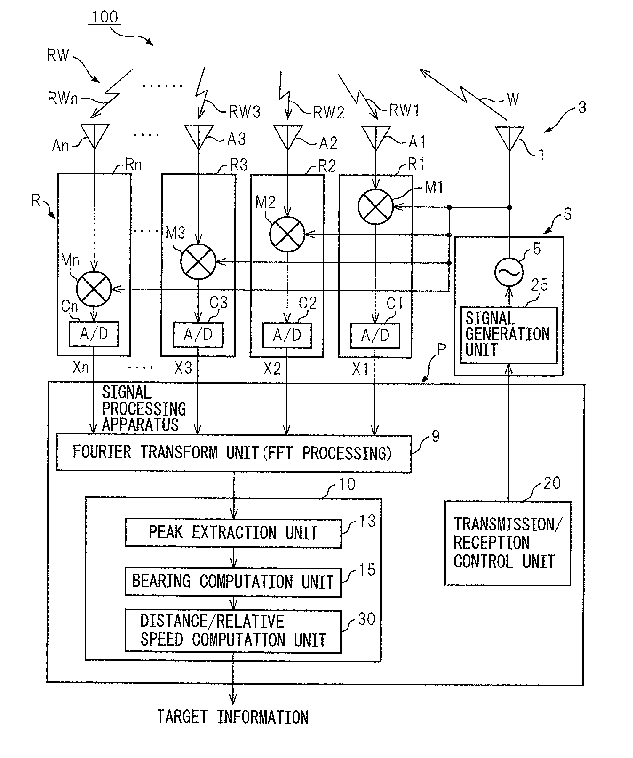
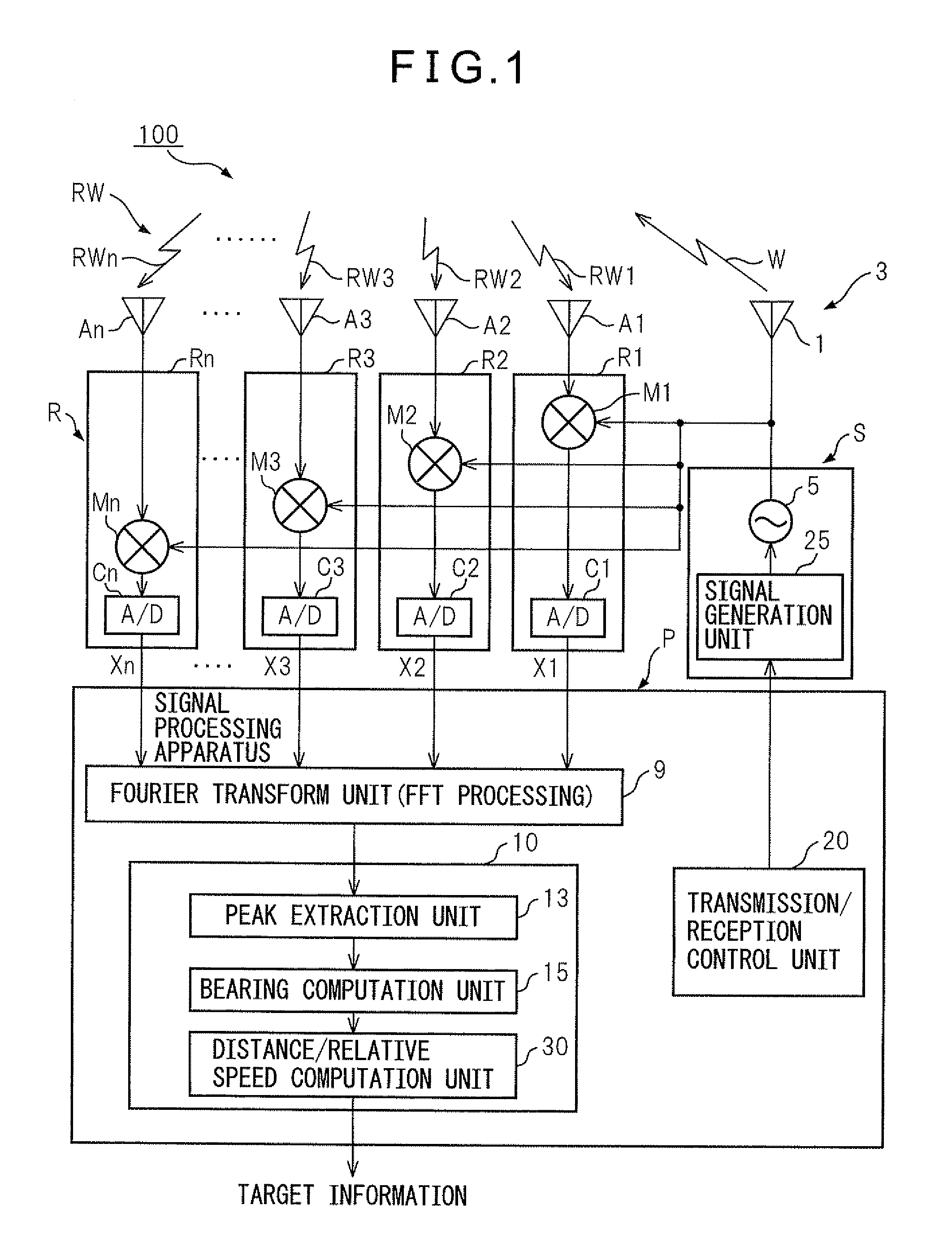
[0045]FIG. 1 shows the configuration of a radar device 100 of one embodiment of the present invention. The radar device 100 of this embodiment is comprised of a sending unit S, a receiving unit R, and a signal processing system P. The signal processing system P, while illustration of the detailed configuration is omitted, is configured provided with a microprocessor. There are also a Fourier transform unit 9, a distance / relative speed processing unit 10, and a sending / receiving control unit 20.

[0046]The sending unit S is provided with an oscillator 5 and a signal generation unit 25. The signal generation unit 25 is controlled by a sending / receiving control unit 20 located at the signal processing system P. The signal generation unit 25 supplies a triangular wave-shaped modulated signal (triangular waves) as the transmit signal to the oscillator 5 ...


PUM


Abstract

An electronic scan type radar device which uses a high resolution performance processing to estimate directions of arrival of radio waves, wherein powers of arrival waves received for targets are accurately calculated, that is, a vehicle-mounted radar device utilizing electronic scan which uses a predetermined angle estimation system to estimate directions of arrival of reflected waves, comprising finding mode vectors for angles calculated from the receive signals of the antennas, decomposing a vector of the receive signals into directions of the mode vectors, and defining the lengths of the decomposed vectors the receive powers of the reflected waves arriving from the targets. Due to this method, even if there are targets, it is possible to accurately calculate the powers of the arrival waves, whereby pairing is accurately performed, the precision of detection of targets is improved, and erroneous operation of a vehicle-mounted radar device utilizing electronic scans is prevented.

Description

CROSS-REFERENCE TO RELATED APPLICATION[0001]This application claims priority from, and incorporates by reference the entire disclosure of, Japanese Patent Application No. 2011-020058 filed on Feb. 1, 2011.BACKGROUND OF THE INVENTION[0002]1. Field of the Invention[0003]The present invention relates to a radar device and a method of calculation of receive power in that radar device, more particularly relates to a radar device which receives radio waves sent from a vehicle and reflected back from a target at a plurality of receive antennas to detect a position of the target and a method of calculation of receive power in that radar device.[0004]2. Description of the Related Art[0005]In the past, there have been radar devices which continuously measure the distance and direction of preceding vehicles or targets in the front (obstacles) or of vehicles or other targets approaching from the rear relative to a vehicle being driven by a user and which prevent collisions or enable automatic d...

Claims


Application Information

Patent Timeline
Patent Type & Authority Applications(United States)
IPC IPC(8): G01S13/02
CPCG01S13/42G01S13/345
Inventor KURONO, YASUHIRO
Owner FUJITSU GENERAL LTD
Why Eureka
Try Eureka