Supercharge Your Innovation With Domain-Expert AI Agents!

Imaging device detecting motion vector

a technology of motion vector and imaging device, which is applied in the field of imaging device detecting motion vector, can solve the problems of reducing the encoding efficiency of motion compensation, the distortion of super-wide-angle lenses, etc., and achieve the effect of improving the detection efficiency of motion vector

Active Publication Date: 2012-08-02
CANON KK
View PDF13 Cites 20 Cited by
  • Summary
  • Abstract
  • Description
  • Claims
  • Application Information

AI Technical Summary

Benefits of technology

The present invention is about a technique for improving the detection of motion vectors in image data. It involves correcting aberration in the image data and detecting motion vectors based on the corrected data. The invention also includes a vector correction unit that corrects errors caused by the aberration correction process. The technique helps to set an appropriate search area for motion vectors and increase the efficiency of detection.

Problems solved by technology

The super-wide-angle lens has great distortion.
Here, when the taken image data is greatly distorted, the motion compensation of the conventional technique causes the following problem.
This disadvantageously causes reduction in encoding efficiency when motion compensation is performed.

Method used


Image

  • Imaging device detecting motion vector
  • Imaging device detecting motion vector
  • Imaging device detecting motion vector

Examples


Embodiment Construction

[0027]Various exemplary embodiments, features, and aspects of the invention will be described in detail below with reference to the drawings.

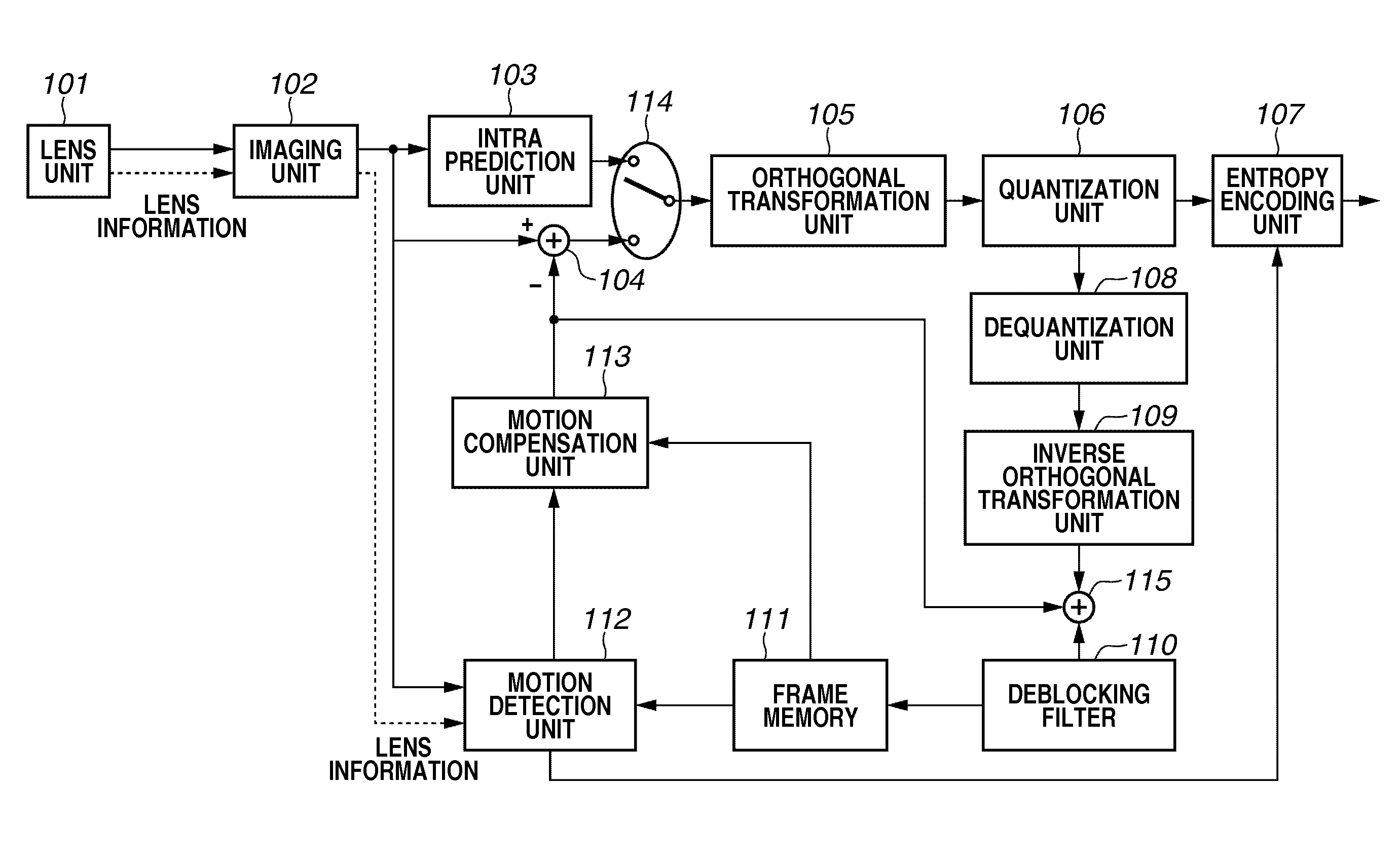
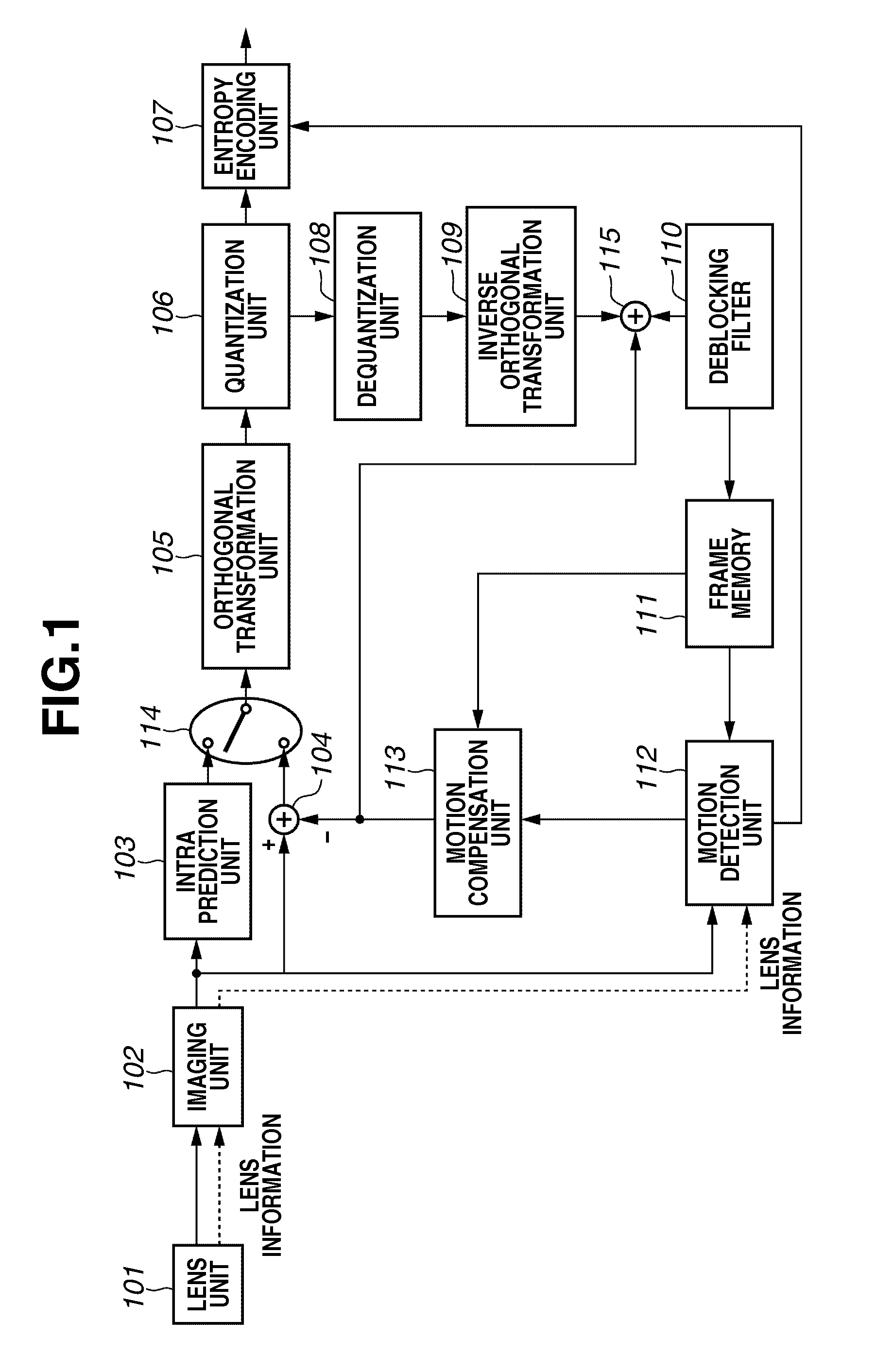
[0028]First, a first exemplary embodiment of the present invention will be described. FIG. 1 illustrates a constitution of an imaging device according to a first exemplary embodiment of the present invention. In particular, FIG. 1 illustrates components related to encoding processing. The exemplary embodiment to be described later includes a constitution employing an encoding system of H.264 as an example.

[0029]As illustrated in FIG. 1, an imaging device according to the exemplary embodiment includes a lens unit 101, an imaging unit 102, an intra prediction unit 103, an adder 104, an orthogonal transformation unit 105, a quantization unit 106, an entropy encoding unit 107, an dequantization unit 108, an inverse orthogonal transformation unit 109, a deblocking filter 110, a frame memory 111, a motion detection unit 112, a motion compensation uni...


PUM


Abstract

An imaging device includes a first detection unit, a vector correction unit, and a second detection unit. The first detection unit is configured to detect a motion vector based on reference image data and input image data after aberration of a lens is corrected. The vector correction unit is configured to correct an error component included in the motion vector detected by the first detection unit according to an aberration characteristic of the lens. The error component is produced by aberration correction. The second detection unit is configured to set a search area of the motion vector based on the motion vector corrected by the vector correction unit and detect the motion vector in the search area.

Description

BACKGROUND OF THE INVENTION[0001]1. Field of the Invention[0002]The present invention relates to a technique for detecting a motion vector from image data generated based on a subject image input through a lens having aberration such as distortion in an imaging device.[0003]2. Description of the Related Art[0004]A digital camcorder and a digital still camera photograph a subject, and encode and store a captured moving image. Examples of the digital camcorder and the digital still camera include an interchange lens type (for example, a digital single-lens reflex camera) having a detachable lens. The lens can be replaced by various lenses such as a telephoto lens and a wide-angle lens according to a photographic scene. Examples of the lens include a super-wide-angle lens referred to as a fisheye lens. The super-wide-angle lens has great distortion. An image captured by the super-wide-angle lens is magnified toward a center of a frame, and is reduced toward a periphery of the frame. On...

Claims


Application Information

Patent Timeline
Patent Type & Authority Applications(United States)
IPC IPC(8): H04N5/228H04N23/40H04N19/105H04N19/136H04N19/139H04N19/189H04N19/423H04N19/46H04N19/50H04N19/503H04N19/513H04N19/533H04N19/57H04N19/593H04N19/60H04N19/61H04N19/70H04N19/80H04N19/91
CPCH04N5/217H04N5/3572H04N19/85H04N19/53H04N19/57H04N19/513H04N23/81H04N25/61
Inventor KAWAKAMI, MASASHIKANEKO, YUSHI
Owner CANON KK
Features
  • R&D
  • Intellectual Property
  • Life Sciences
  • Materials
  • Tech Scout
  • Unparalleled Data Quality
  • Higher Quality Content
  • 60% Fewer Hallucinations
Learn More