[0011]As indicated above, the invention concerns a conveying system where items via an airflow in a tube connection are conveyed in the direction of the airflow. A feature of a conveying system according to the invention is that the tube connection has an inner cross-sectional area, preferably a circular cross-sectional area, of a size greater than the largest cross-sectional area of an elongated item measured transversely of the longitudinal direction of the item, and which preferably is provided with at least twice the cross-sectional area compared with the largest cross-sectional area of the item, where the items have a length which is greater than the largest inner cross-dimension /
diameter /
diagonal. By such a solution it is possible to convey an item in the tube connection if there is an excess of air with a relatively small
overpressure. By conducting a large amount of air through the tube system, the air may lift and convey the item over distances of several hundred meters. At the same time, there is achieved the
advantage that several items may be conveyed in the same tube connection simultaneously as there is such an excess of air that it does not influence the efficiency of the system to an appreciable degree. As mentioned, it is possible to perform conveying of up to a plurality of items at a time where these items are sent individually and successively corresponding to one item being sent immediately after the other. A further
advantage of a system as mentioned is that the items are sent with a certain orientation and that the items also arrive at a receiver station with the same orientation. Thus there is no need for staff to use time on turning items end on end before further dispatching or
processing. This is a significant advantage since a receiver station may thus operate automatically more easily, thereby reducing the
workload on the staff and the costs of the avoided sorting.
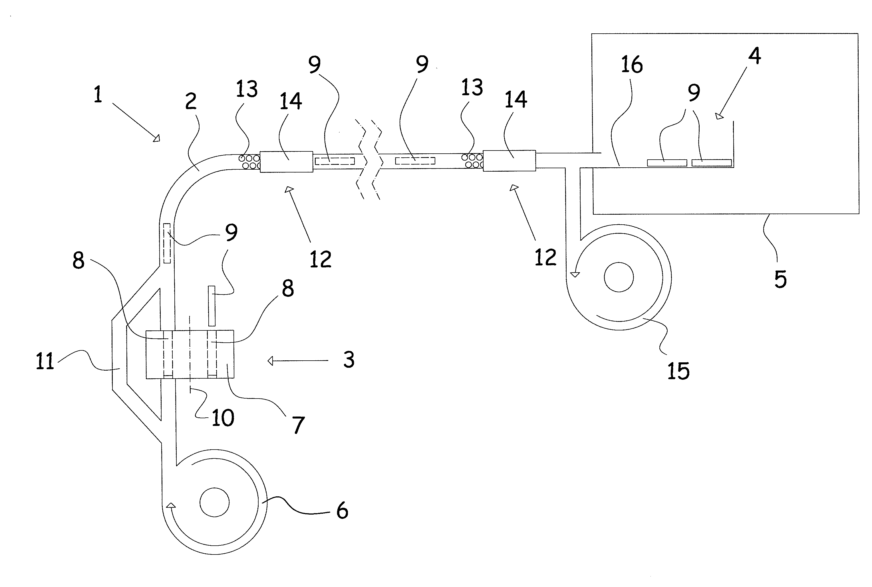
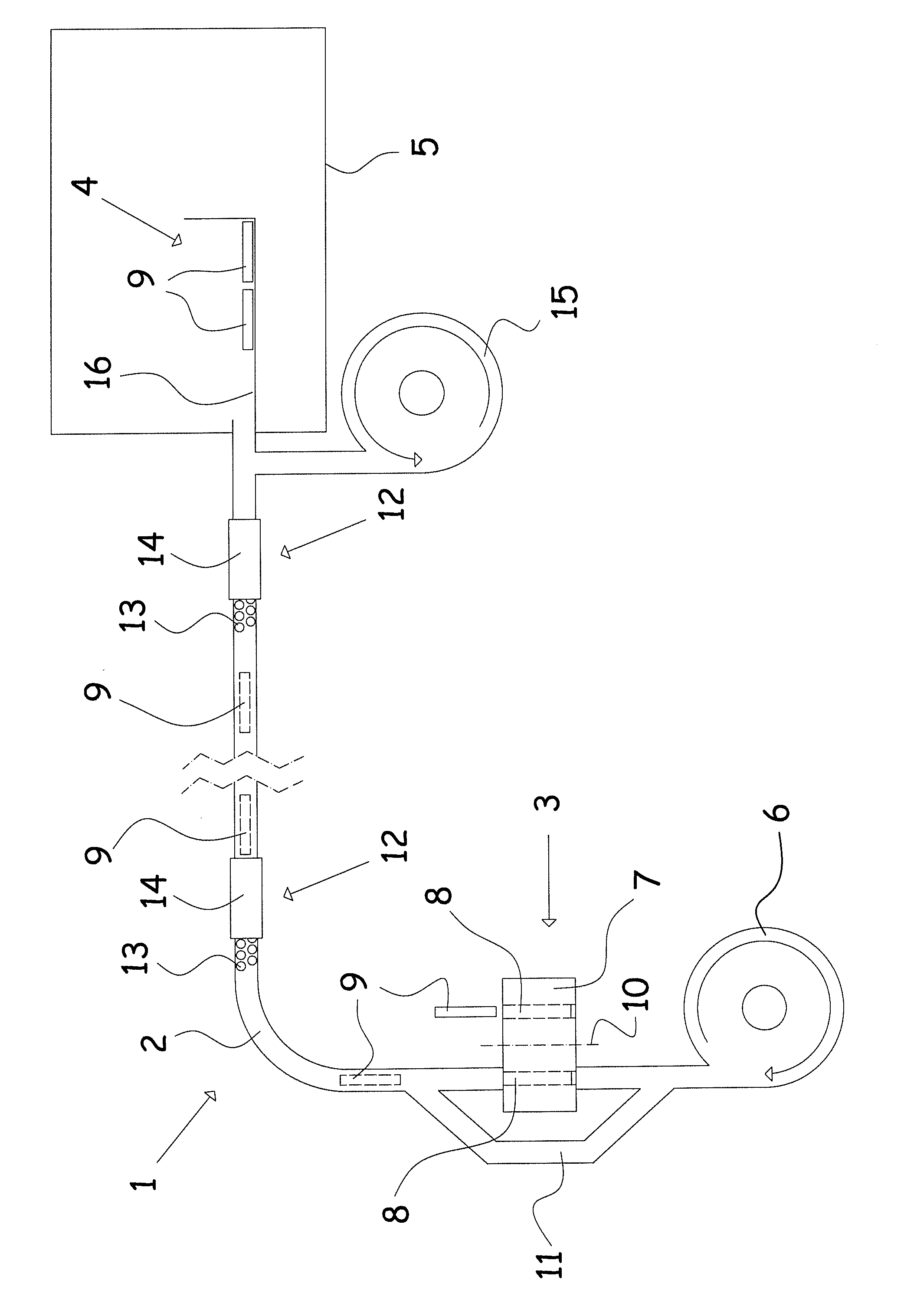
[0015]In an embodiment of a conveying system according to the invention, the conveying system may advantageously include a dispatch station which includes a holder for the at least one item, where the at least one item is placed in a cutout in this holder, where the cutout in the holder in connection with sending the item is displaced into the airflow in the tube connection and is flushed by an airflow, where the airflow is generated by a mechanical blower device. By such a dispatch station, items may be dispatched without opening for the airflow in the tube connection. Actually, the holder may be designed as a revolving drum with a number of cutouts that are brought into the airflow one by one. By such a solution, a large number of items may be dispatched in succession. By having a cutout in the airflow all the time, there is achieved the obvious advantage that the airflow is not disturbed substantially while at the same time a rapid dispatching of items may be effected.
[0017]A conveying system according to the invention may advantageously be provided with a tube connection that further includes a mechanical suction device by which air is sucked and conducted away, where the air is sucked out immediately before a receiver station. Hereby is achieved the advantage that no
overpressure is built up in the room in which the receiver station is established as the amount of air sucked out preferably at least corresponds to the amount of air supplied to the tube connection. This may e.g. be in a laboratory where it is not desired that air, possibly contaminated, is introduced. This security may be achieved by removing e.g. 10% more air at the receiver station than supplied from the dispatch station. This will also impart a decelerating action on the conveyed items, and thereby a more gentle reception of the latter is achieved.
[0020]The
conveyor system according to the invention may be designed such that the at least one tube connection is made of tubing or hose, preferably of tubing or hoses of plastic or
metal. These tubes or hoses may be used for vertical as well as horizontal and oblique mounting as the
overpressure in the tube connection will ensure that the item is brought forward regardless of the direction of conveying being up, down or along. By using hoses with long length and with a certain flexibility, easy mounting with a minimum of joints in the tube connection is achieved. However, in connection with systems where the tube connection may be several hundred meters long, maybe up to 1000 m, for mounting reasons there are obviously to be a number of joints along the length. These joints are made with great care in order to avoid possible internal edges and / or displacements that may cause braking of items. Another important parameter is the
surface roughness or the
friction coefficient on the inner surface in the tube connection and on the item. Depending on the friction in the tube connection between the inner surface and the item, and the weight of the item, air pressure and airflow may be regulated to optimum.
[0022]A conveying system according to the invention may advantageously be used for conveying items where the items are constituted by the material to be conveyed. Thus there is no need for putting the item into a special capsule adapted to be conveyed in the tube connection. Hereby is achieved the obvious advantage that the conveying system is easier and faster in use as no time is used in putting the item into a capsule and taking the item out of this capsule. At the same time there is no need to ensure the presence of available capsules at the dispatch stations.
[0024]By using a conveying system according to the invention, e.g. in a hospital for transporting blood samples from a location close to a sampling site and to a laboratory where the blood sample is to be examined more closely, a much faster
processing time is attained since the sampler may continuously send the samples to closer examination and not, as normally, take out a number of samples and subsequently deliver all the samples collectively to the laboratory. As there are often long distances in a hospital, a conveying system according to the invention may be used with advantage since the transport of a blood sample can occur rapidly after which the sample can be examined correspondingly rapidly. At the same time there is the advantage that the tasks continuously come to the laboratory and therefore also may be analysed continuously, implying a markedly reduced consumption of resources.

