Packaging material with integrated pressure relief valve

a pressure relief valve and packaging material technology, applied in the field of packaging materials, can solve the problem of rather high opening pressure of the valve, and achieve the effects of reducing the force needed for elongating the test, and facilitating the sealing of the valv

Active Publication Date: 2012-08-02
AMCOR FLEXIBLES TRANSPAC B V B A
View PDF1 Cites 8 Cited by
  • Summary
  • Abstract
  • Description
  • Claims
  • Application Information

AI Technical Summary

Benefits of technology

[0009]When the packaging material is not subjected to an excessive internal pressure or subjected to a minor pressure, the pressure relief valve remains its normally closed position, wherein the liquid in the channel or pocket portion provides adhesiveness between the inner film and the outer film so as to prevent an open connection between the inlet opening and the outlet opening. In the closed position of the valve ambient air is also prevented from penetrating from the outlet opening to the inlet opening and thereby into the interior of a package of which at least a part is formed of the packaging material. When the pressure in the package increases due to gasses being released from the packed product and reaches the predetermined excess pressure, the outer film is forced away from the inner film and the adhesiveness of the liquid film is reduced to provide an open connection between the inlet opening and the outlet opening. As a result, the excess pressure is relieved until a closing pressure is obtained allowing the outer film to flex back into the closed position of the valve, thereby preventing air from the ambience to penetrate into the interior of the package through the outlet opening, the channel portion and the inlet opening.
[0010]Especially the elasticity of the outer film allows for an opening of the valve at a low excess pressure and a reliable closure of the valve at a pressure being lower than the predetermined excess pressure. Tests have shown that it is possible to provide an opening pressure of less than 4 mbar and a reliable closing of the valve when the excess pressure has been relieved by venting of generated gasses through the valve. The tensile tests have been carried out on an Instron 5564.
[0011]Additionally it should be noted that flexible packages, i.e. packages being formed entirely of the packaging material, such as flexible bags subjected to rough handling during packing at the factory and later when they are unpacked at a shop. Due to its softness and flexibility the outer film is able to follow the inner film during rough handling and thereby maintains the functionality of the valve of the packaging material.
[0012]According to the invention the force needed to elongate the test piece of the second film by 5% is less than 4N, alternatively less than 3N, alternatively less than 2N, alternatively less than 1.5 N and optionally less than 1N. A decrease in the force needed for elongating the test piece by 5% allows for a decrease of the opening pressure of the valve, i.e. allows for a very low opening pressure of the valve.

Problems solved by technology

However, when using such films for the outer film in a packaging material with an integral valve, the opening pressure of the valve is rather high due to the stiffness or comparatively low elasticity of these films.

Method used


Image

  • Packaging material with integrated pressure relief valve
  • Packaging material with integrated pressure relief valve
  • Packaging material with integrated pressure relief valve

Examples


first embodiment

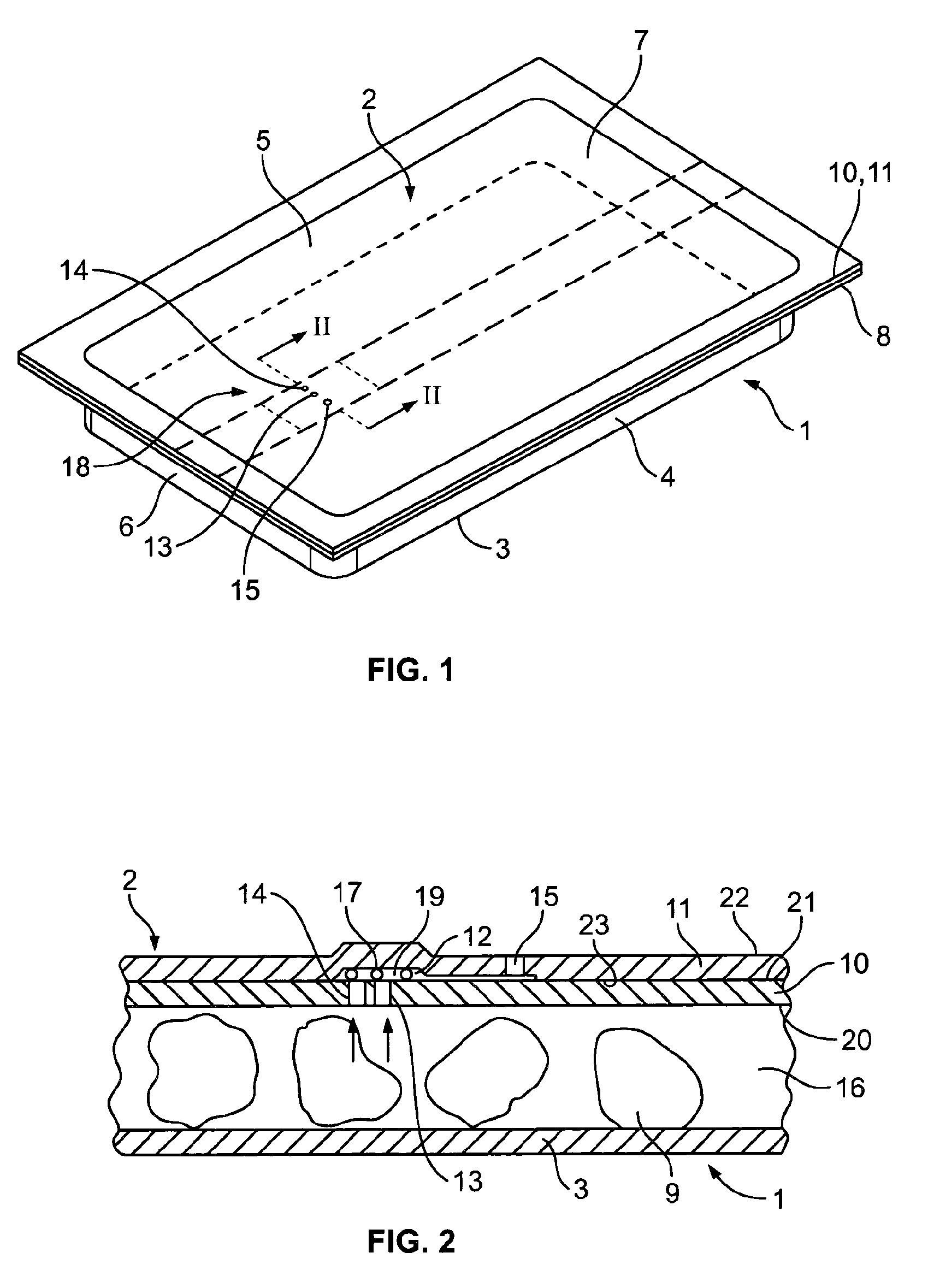
[0051]The package shown in FIGS. 1 and 2 includes a bowl-shaped lower part 1 and planar cover part or lid 2, the latter being formed of packaging material according to the invention.

[0052]The lower part is rectangular and includes a bottom 3. Two pairs of opposing lateral walls 4, 5 and 6, 7 extend upwardly from the bottom 3. At their upper ends the lateral walls continue into a common flange 8. The lower part is typically made from polypropylene (PP) and made by thermoforming or injection moulding.

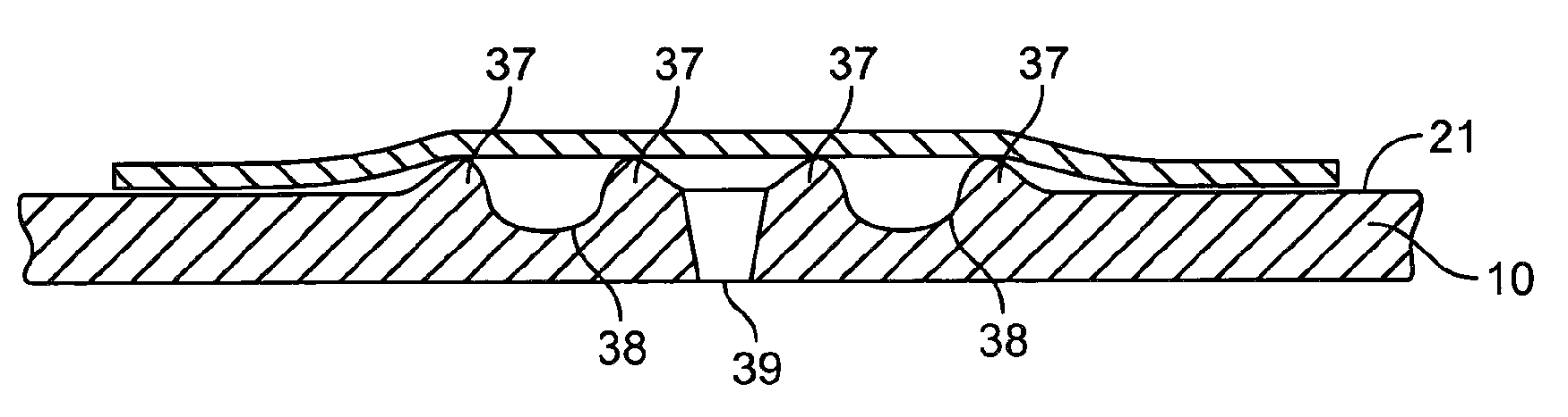
[0053]The planar cover part 2 is sealed to the flange of the lower part 1 to form a closed inner chamber 16 in which a food product releasing gasses is housed. For reason of clarity the food product is not shown in FIG. 1 but only in FIG. 2. The packaging material from which the cover part 2 is formed comprises a first inner film 10 having a first surface 20 and a second surface 21, and a second outer film 11 having a first surface 22 and a second surface 23. The two films are laminated t...

second embodiment

[0063]Before describing the structure of the packaging material and the pressure relief valve thereof in details, it should be noted that the bag formed by the packaging material in known manner has a back seal 25, a bottom seal 26 and a top seal 27. The said three seals 25, 26, 27 are shaped as fin seals, i.e. the packaging material is sealed inner face to inner face (PE 60 against PE 60). The seals provide a sealed inner chamber 28 housing a food product releasing gasses. The food product is not shown in FIGS. 3-5.

[0064]Now reverting to the structure of the packaging material, the inner film 10 is provided with five inlet openings 28 arranged as the pips of the five side of a dice, i.e. so as to form an X. As an example each of the inlet openings 28 may have a diameter of about 150 μm and interspaced by about 0.75 mm. The inlet openings 28 are cut by means of laser beam from the second surface 21 of the inner film 10, whereby a small protrusion 29 is automatically formed along the...


PUM

PropertyMeasurementUnit
widthaaaaaaaaaa
elongationaaaaaaaaaa
speedaaaaaaaaaa

Abstract

A packaging material for forming at least a part of a package for a product releasing gasses comprises a one-way pressure relief valve (18) including a first inner film (10), being provided with at least one inlet opening (13,14) therethrough, and a second outer film (11) covering the at least one inlet opening (13, 14) and being bonded to the first inner film (10) to form a channel portion (12) between the inner and the outer film. The channel portion (12) communicates with the surroundings of the package through at least one outlet opening (15) spaced apart from the at least one inlet opening (13, 14). The pressure relief valve (18) further comprises a liquid (19) provided in the channel portion (12) and solid spacer means (17) provided in the channel portion (12) proximate to the at least one inlet opening (13, 14). The outer film (11) is a soft film having such a flexibility or elasticity that in a tensile test a force of less than 5 N is needed for elongating a test piece thereof having a width of 15 mm by 5%.

Description

TECHNICAL FIELD[0001]The present invention relates to a packaging material for forming at least a part of a package for a product releasing gasses, especially a food product, and being provided with an integral, normally closed pressure relief valve opening at a predetermined excess pressure, said pressure relief valve including a first inner film, preferably a polymer film, to be an inner film of the package and being provided with at least one inlet opening therethrough, and a second outer film, preferably a polymer film, to be an outer film of the package and covering the inlet opening in the first inner film and being bonded to the first inner film to form a channel or pocket portion between the first inner and the second outer film, said channel or pocket portion communicating with the surroundings of the package through at least one outlet opening spaced apart from the inlet opening, the first inner film having a first surface and a second surface and the second outer film hav...

Claims


Application Information

Patent Timeline
Patent Type & Authority Applications(United States)
IPC IPC(8): B32B1/02B32B3/10
CPCB32B3/08B32B3/266B65D77/225Y10T428/24322Y10T428/1379Y10T428/1352Y10T428/1324Y10T428/24744Y10T428/24331Y10T428/1334Y10T428/1341B32B5/142B32B27/08B32B27/306B32B27/32B32B27/36B32B3/28B32B3/30B32B2250/24B32B2255/10B32B2255/205B32B2270/00B32B2274/00B32B2307/51B32B2307/54B32B2307/546B32B2307/7242B32B2435/02B32B2439/70B32B7/05Y10T428/249995Y10T428/31504
Inventor HANSEN, PETERLYKKE, KIRSTEN
Owner AMCOR FLEXIBLES TRANSPAC B V B A
Why Eureka
Try Eureka