Uniform dry etch in two stages

a technology of dry etching and dry etching, which is applied in the direction of basic electric elements, semiconductor/solid-state device manufacturing, electric devices, etc., can solve the problem of not readily etching silicon

Active Publication Date: 2012-08-02
APPLIED MATERIALS INC
View PDF4 Cites 243 Cited by
  • Summary
  • Abstract
  • Description
  • Claims
  • Application Information

AI Technical Summary

Benefits of technology

[0007]A method of etching silicon oxide from a multiple trenches is described which allows more homogeneous etch rates among trenches. The surfaces of the etched silicon oxide within the trench following the etch may also be smoother. The method includes two dry etch stages followed by a sublimation step. The first dry etch stage removes silicon oxide quickly and produces large solid residue granules. The second dry etch stage remove silicon oxide slowly and produces small solid residue granules in amongst the large solid residue granules. Both the small and large solid residue are removed in the ensuing sublimation step. There is no sublimation step between the two dry etch stages.

Problems solved by technology

The Siconi™ etch is largely conformal and selective towards silicon oxide layers but does not readily etch silicon regardless of whether the silicon is amorphous, crystalline or polycrystalline.

Method used


Image

  • Uniform dry etch in two stages
  • Uniform dry etch in two stages
  • Uniform dry etch in two stages

Examples


Embodiment Construction

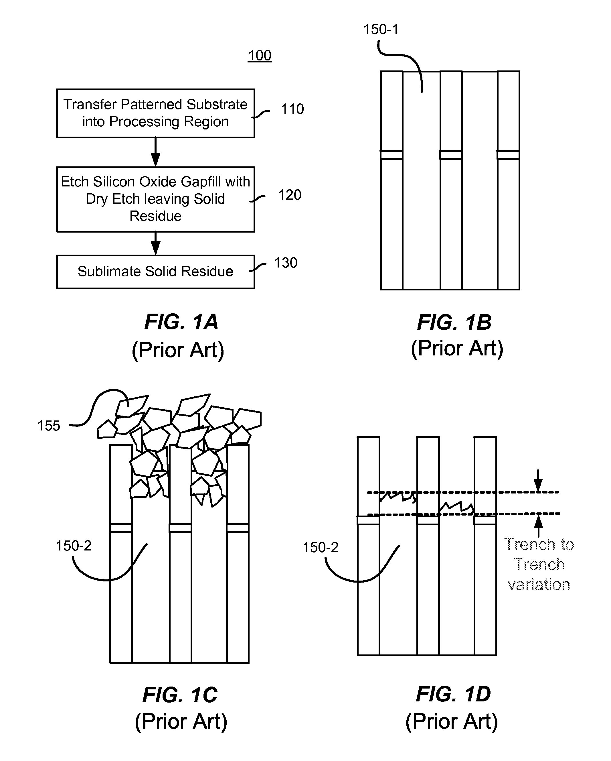
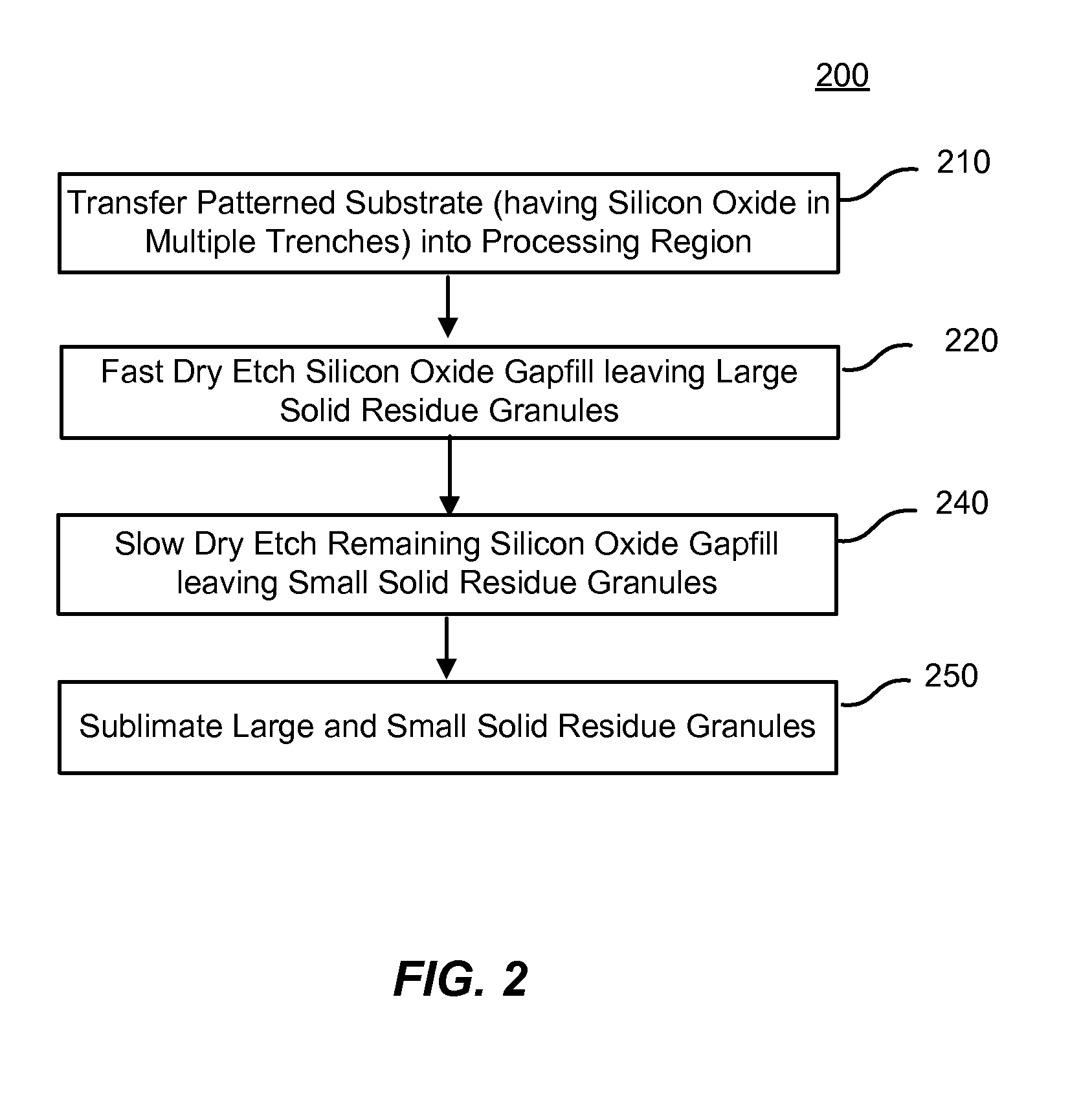
[0017]A method of etching silicon oxide from a multiple trenches is described which allows more homogeneous etch rates among trenches. The surfaces of the etched silicon oxide within the trench following the etch may also be smoother. The method includes two dry etch stages followed by a sublimation step. The first dry etch stage removes silicon oxide quickly and produces large solid residue granules. The second dry etch stage remove silicon oxide slowly and produces small solid residue granules in amongst the large solid residue granules. Both the small and large solid residue are removed in the ensuing sublimation step. There is no sublimation step between the two dry etch stages.

[0018]Siconi™ etch processes are an example of a dry etch process and have used a hydrogen source such as ammonia (NH3) in combination with a fluorine source such as nitrogen trifluoride (NF3). The combination flows into a remote plasma system (RPS) and the plasma effluents created therein are flowed into...


PUM


Abstract

A method of etching silicon oxide from a multiple trenches is described which allows more homogeneous etch rates among trenches. The surfaces of the etched silicon oxide within the trench following the etch may also be smoother. The method includes two dry etch stages followed by a sublimation step. The first dry etch stage removes silicon oxide quickly and produces large solid residue granules. The second dry etch stage remove silicon oxide slowly and produces small solid residue granules in amongst the large solid residue granules. Both the small and large solid residue are removed in the ensuing sublimation step. There is no sublimation step between the two dry etch stages.

Description

CROSS-REFERENCES TO RELATED APPLICATIONS[0001]This application claims the benefit of U.S. Provisional Patent Application No. 61 / 422,942 filed Dec. 14, 2010, which is incorporated herein by reference in its entirety for all purposes.BACKGROUND OF THE INVENTION[0002]Integrated circuits are made possible by processes which produce intricately patterned material layers on substrate surfaces. Producing patterned material on a substrate requires controlled methods for removal of exposed material. Chemical etching is used for a variety of purposes including transferring a pattern in photoresist into underlying layers, thinning layers or thinning lateral dimensions of features already present on the surface. Often it is desirable to have an etch process which etches one material faster than another helping e.g. a pattern transfer process proceed. Such an etch process is said to be selective to the first material. As a result of the diversity of materials, circuits and processes, etch proces...

Claims


Application Information

Patent Timeline
Patent Type & Authority Applications(United States)
IPC IPC(8): H01L21/3065
CPCH01L21/31116H01L21/3065
Inventor YANG, DONGQINGTANG, JINGINGLE, NITIN
Owner APPLIED MATERIALS INC
Why Eureka
Try Eureka