
Self-cleaning flooring system

a flooring system and self-cleaning technology, applied in the field of flooring protection, can solve the problems of difficult if not impossible maintenance of cleanliness, frequent spillage of waste products on kitchen flooring in restaurants, hotels, commercial food vending facilities in general, and the lik

Inactive Publication Date: 2012-08-09
SANI FLOOR INC
View PDF7 Cites 20 Cited by
  • Summary
  • Abstract
  • Description
  • Claims
  • Application Information

AI Technical Summary

Benefits of technology

"The present invention is an improved self-cleaning flooring system for catching waste products. The system includes a drain pan and a floor grid that support personnel and animals while allowing waste products to pass through. The drain pan has ramps and a drain channel with discharge mechanisms for flushing fluid onto the ramp. The floor grid has abutting grids that can be interconnected. The system can be cleaned using commercial dishwashing equipment. The flushing fluid flows from the inlet to the drain outlet, carrying waste products with it. The system helps to keep the floor clean and prevents waste products from entering the drain pan."

Problems solved by technology

The kitchen flooring in restaurants, hotels, institutions, and commercial food vending facilities in general is subject to frequent spillage from waste products.
Spilled waste products may create a sanitation hazard as a hot kitchen is a natural breeding ground for harmful bacteria that may be caught in tile grout, and around pipes, drains or other kitchen fixtures.
Because of the immovable nature of such kitchen fixtures, cleanliness is difficult if not impossible to maintain.
Daily cleaning of walls, counter tops, appliances and floors involves a great deal of hand labor consuming a considerable amount of time.
In addition, the waste products may create a health hazard in that spilled food products are often wet or sticky, creating a high risk that kitchen personnel may be injured in a fall.
Furthermore, spilled grease or oil creates a fire safety hazard requiring the cessation of all operations in the kitchen until the grease or oil is removed from the floor.
As may be expected, shutting down all kitchen operations in a restaurant or hotel may result in a significant loss of revenue.
In addition, current cleaning methods of facilities such as commercial kitchens may entail the temporary removal and / or dismantling of certain equipment and flooring systems followed by lengthy washing with water.
As may be appreciated, such cleaning methods results in the use of large quantities of water which may increase water conservation issues in certain locales.
Although the device addresses a few safety and sanitation issues mentioned above in that it provides a disposal means for fluid waste, the device lacks installation flexibility in that it must be custom fitted to a particular floor configuration.
In addition, the size of the grids and sub-floor are such that these components are too heavy and too large to be individually washed, either by hand or by mechanical means, such as in a commercial dishwasher.
However, a major drawback to the device is that a large portion of the subsurface of the flooring member is in direct contact with the moist support floor.
Although this device addresses some safety concerns in that it provides a non-slip surface upon which personnel may stand, the device is subject to the problems of mildew and degradation of the subfloor arising from captured water.
Furthermore, the device is not configured to be easily washable by hand or by mechanical means.
Finally, the above-mentioned devices require the use of large amounts of water for thorough cleaning thereof.

Method used


Image

  • Self-cleaning flooring system
  • Self-cleaning flooring system
  • Self-cleaning flooring system

Examples


first embodiment

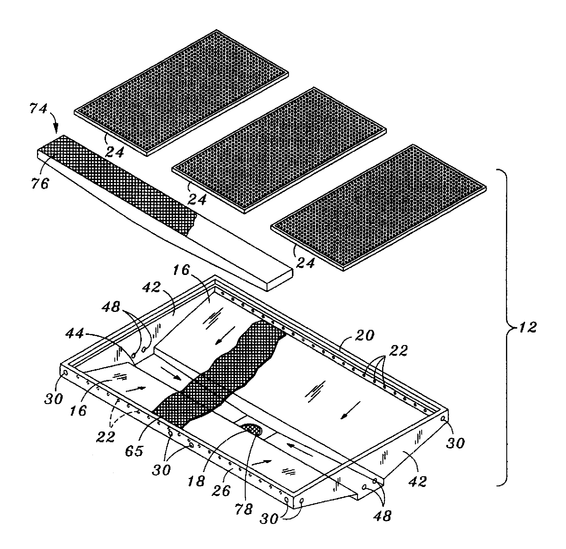
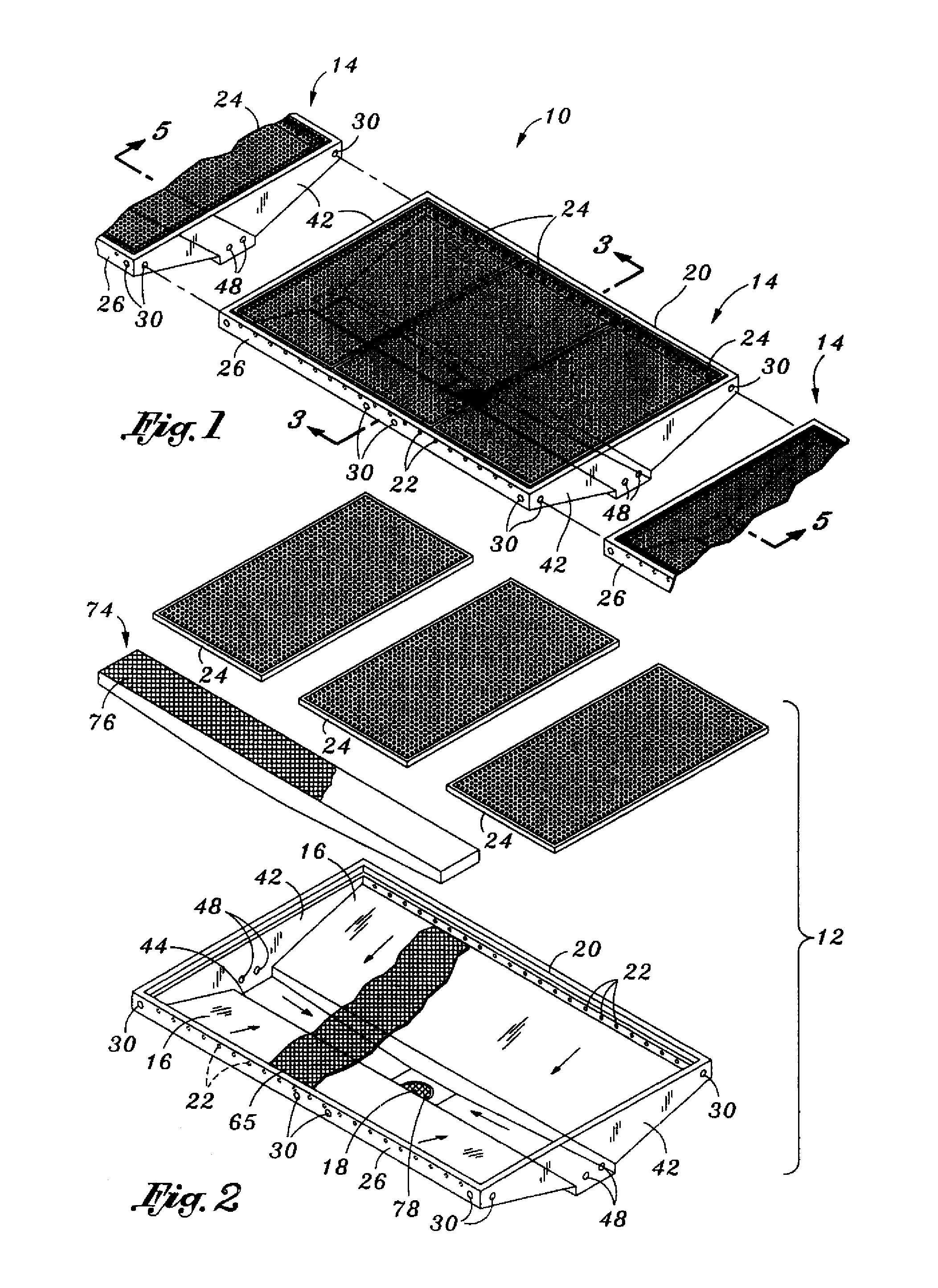
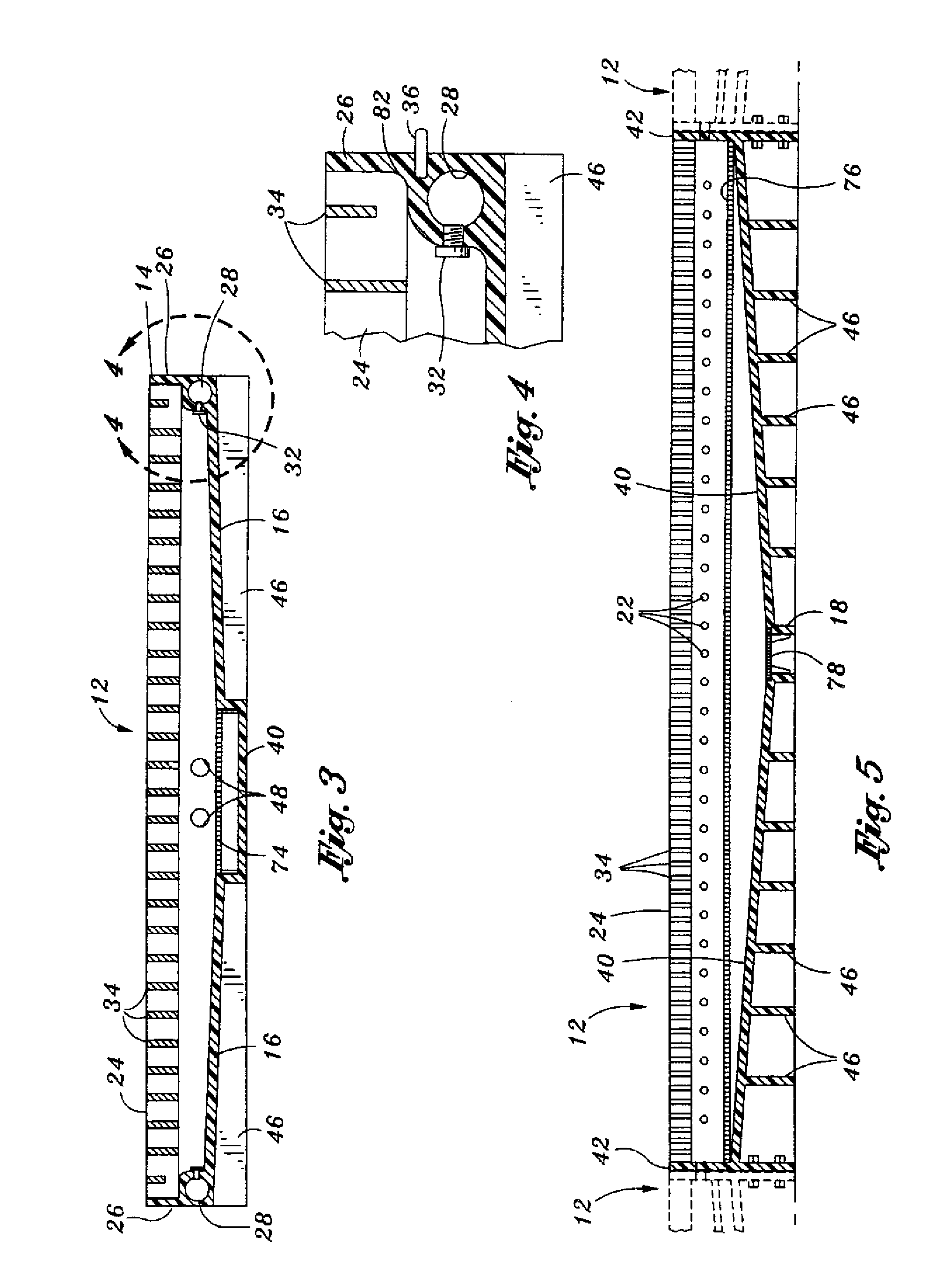
[0062]Turning now to FIG. 5, shown in a transverse sectional view of the module 12 of the first embodiment taken along line 5-5 of FIG. 1 and illustrating the drain channel 40 sloping downwardly toward the drain outlet 18. In FIG. 5, the rib members 46 can be seen extending vertically downwardly from the ramp 16 lower surface. Discharge ports 22 can be seen disposed within the side wall 26 and extending along the length thereof. The discharge ports 22 may be evenly spaced between the end walls 42 although any spacing is contemplated for the discharge ports 22.

[0063]The strainer tray 74 is shown disposed above or mounted within the drain channel 40 which extends from end wall 42 to end wall 42. As was earlier mentioned, the strainer tray 74 includes a grate 76 which prevents the entry of solid or semisolid waste products into the drain channel 40 which may otherwise fall into the drain outlet 18 resulting in clogging thereof. As a final measure of protection, a removable drain basket...

second embodiment

[0066]Turning now to FIGS. 6 and 7, shown is a self-cleaning flooring system 10 which, as was earlier mentioned, comprises at least one module 12, but preferably comprises a series of modules 12 joined end-to-end. Each one of the modules 12 comprises a drain pan section 66 which is itself comprised of a pair of first and second ramp sections 50, 52, and a channel section 54 which is disposed between the first and second ramp sections 50, 52. As shown in FIGS. 6 and 7, the first ramp section 50 is joined to the second ramp section 52 which is interconnected to the channel section 54. The channel section 54 is preferably configured to removably interconnect the first and second ramp sections 50, 52 together at a lower side portion 58 of each one of the first and second ramp sections 50, 52.

[0067]As was mentioned for the configuration in FIGS. 1-5, the first and second ramp sections 50, 52 slope downwardly toward the channel section 54. The module 12 shown in FIGS. 6 and 7 is also comp...


PUM


Abstract

A self-cleaning flooring system is provided that includes at least one module. The module comprises a drain pan, a plurality of discharge ports, and at least one side wall. The drain pan may have a ramp and a drain outlet. The ramp may slope downward towards the drain outlet. The discharge ports may be disposed about a periphery of the drain pan and may be directed towards the drain outlet to direct flushing fluid towards the drain outlet. The side wall may circumscribe a portion of the periphery of the drain pan and include a hollow passage and at least one fluid inlet. The fluid inlet may be in fluid communication with the hollow passage for delivering flushing fluid to the discharge ports.

Description

CROSS-REFERENCE TO RELATED APPLICATIONS[0001]This application is a continuation-in-part of co-pending U.S. application Ser. No. 10 / 282,393, filed Oct. 29, 2002, and co-pending U.S. application Ser. No. 11 / 074,814, filed Mar. 8, 2005, the entire contents of which are hereby incorporated by reference.STATEMENT RE: FEDERALLY SPONSORED RESEARCH / DEVELOPMENT[0002]Not ApplicableBACKGROUND[0003]The present invention relates generally to flooring protection and, more particularly, to a self-cleaning flooring system having modules which are interconnectable to horizontally adjacent modules to form a continuous flooring system for catching waste products in a variety of applications and industries including, but not limited to, laundry facilities and food preparation facilities. The flooring system of the present invention may also be formed as a permanent installation that is cast in a concrete floor using removable male mold inserts that duplicate the shape of a drain pan and over which floo...

Claims


Application Information

Patent Timeline
Patent Type & Authority Applications(United States)
IPC IPC(8): E04B5/48E04H14/00
CPCA01K1/0103A01K1/0151E04F19/10E04F17/00E03F3/046
Inventor MACLEAN, JAMES G.CHRISTIAN, DAVID L.
Owner SANI FLOOR INC
Learn More