
Volume control valve

Active Publication Date: 2012-08-09
EAGLE INDS
View PDF6 Cites 49 Cited by
  • Summary
  • Abstract
  • Description
  • Claims
  • Application Information

AI Technical Summary

Benefits of technology

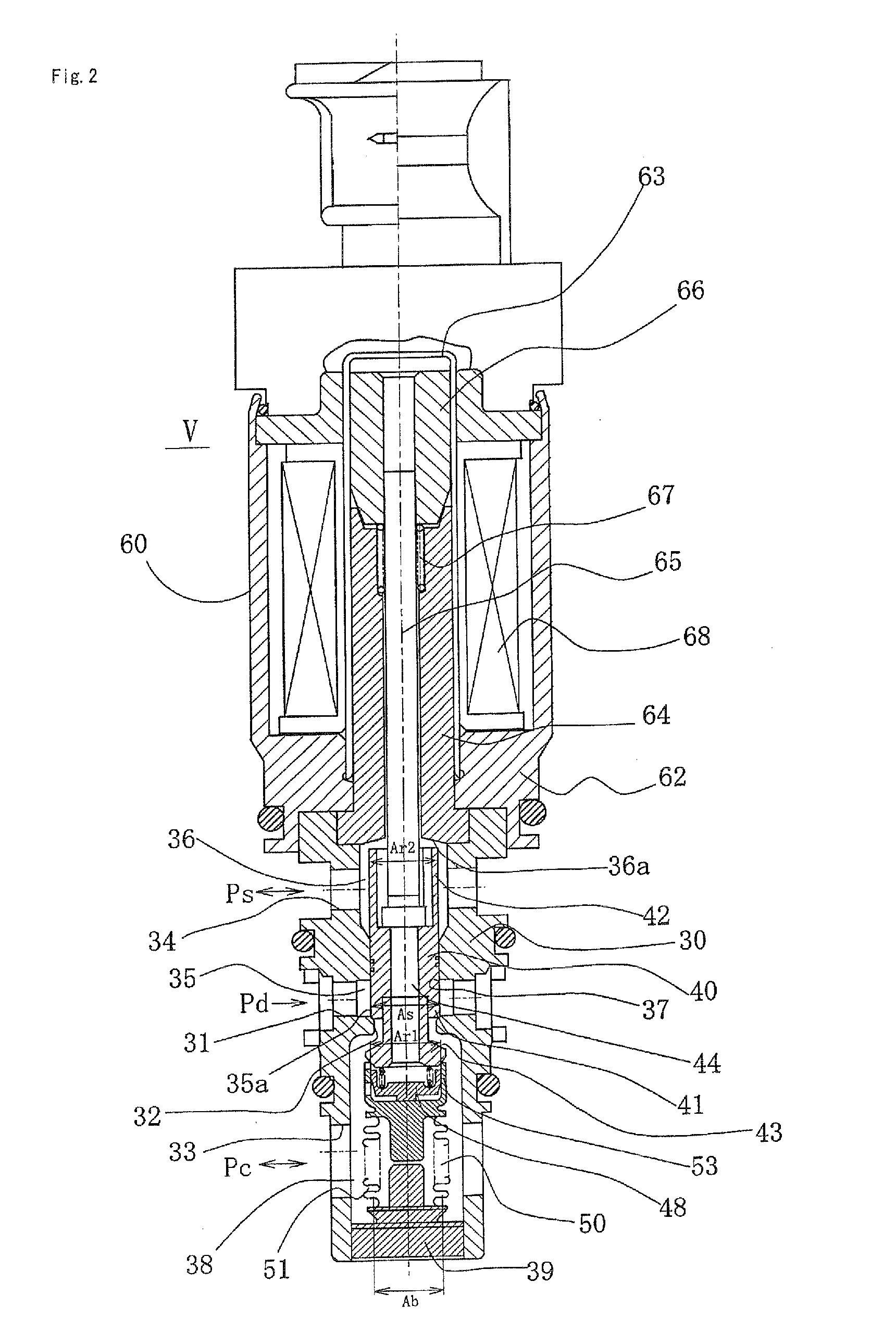
[0039](1) An enhanced state can be maintained for the function to discharge the liquid refrigerant in the control chamber during startup of the variable capacity compressor, an enhanced state can be maintained for the pressure discharge efficiency during maximum capacity, and the control speed of the swash plate during regular control and minimum capacity operation can be improved by providing:
[0040]an adapter provided to a free end of the pressure-sensitive body in the elongation and constriction direction, the adapter having an annular bearing surface, and
[0041]a valve body for discharging a liquid refrigerant, moveably provided inside the adapter;
[0042]wherein a slit is provided to an engaging part of the adapter with the third valve part, an introduction hole for causing the control chamber pressure to act on a bottom surface of the valve body for discharging the liquid refrigerant is provided to the base part side, and urging means is provided whereby the valve body for discharging the liquid refrigerant is urged in a valve-opening direction away from the third valve part.
[0043](2) The seal diameter between the valve body for discharging the liquid refrigerant and the third valve part can be adjusted by forming a contact surface that the valve body for discharging the liquid refrigerant has with the third valve part in a tapered shape.
[0044](3) The effect of the pressure difference between the control chamber pressure Pc and the suction chamber pressure Ps can be applied to the maximum by mounting a Y-ring to an external periphery of the valve body for discharging the liquid refrigerant, and sealing the space between the valve body and the inner surface of the adapter.

Problems solved by technology

It is therefore unavoidable that the variation in control chamber pressure Pc relative to the variation in suction pressure Ps is slower than in Prior Art 1, as shown by the dashed line in FIG. 7, and the problem of the lower control speed of the swash plate during control cannot be resolved.

Method used


Image

  • Volume control valve
  • Volume control valve
  • Volume control valve

Examples


Embodiment Construction

[0054]The modes of working the capacity control valve according to the present invention are described in detail with reference to the drawings, but various changes, modifications, and improvements are possible within the scope of the present invention based on the knowledge of one skilled in the art, without limiting the interpretation of the present invention.

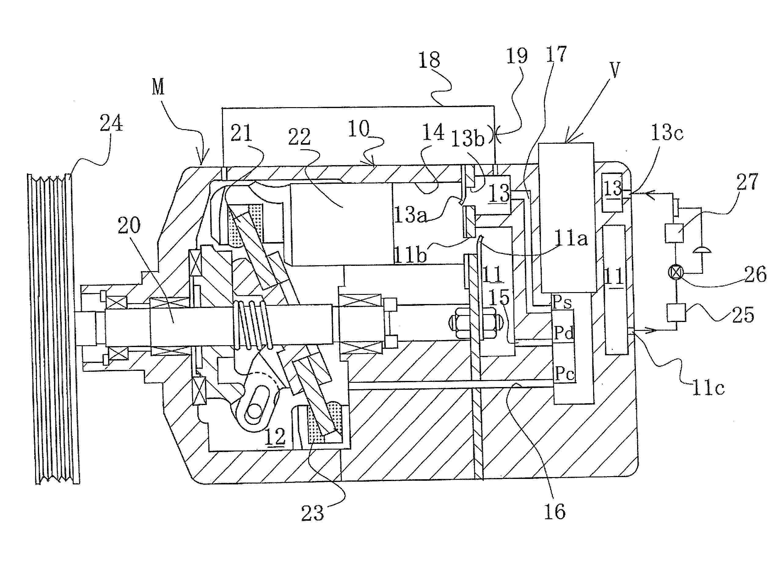
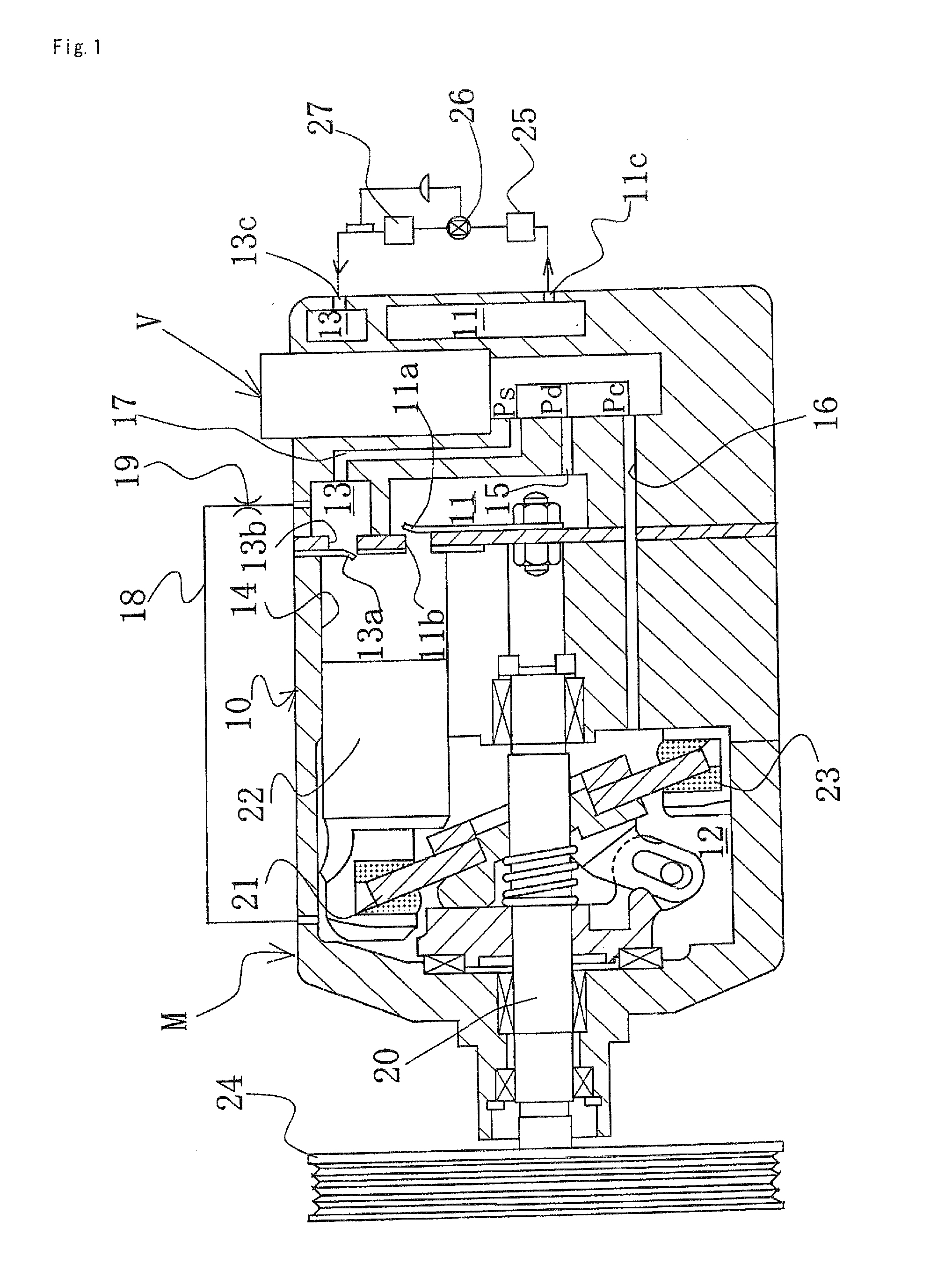
[0055]A variable capacity swash plate compressor M is provided with a discharge chamber 11; a control chamber (also referred to as a crank chamber) 12; a suction chamber 13; a plurality of cylinders 14; a port 11b opened and closed by a discharge valve 11a and used to provide communication between the cylinders 14 and the discharge chamber 11; a port 13b opened and closed by a suction valve 13a and used to provide communication between the cylinders 14 and the suction chamber 13; a discharge port 11c and a suction port 13c connected to an external cooling circuit; a communication passage 15 used as a discharge-side passage fo...


PUM


Abstract

A capacity control valve capable of enhancing the function of discharging liquid refrigerant in a control chamber during startup of a variable capacity compressor, and improving the control speed of a swash plate during control is provided. The valve has an adapter that has an annular bearing surface and is provided to a free end of a pressure-sensitive body in the elongation and constriction direction, and a valve body for discharging liquid refrigerant, moveably provided inside the adapter. A slit is provided to an engaging part of the adapter with a third valve part, and an introduction hole for causing the control chamber pressure to act on a bottom surface of the valve body for discharging the liquid refrigerant is provided to the base part side, and an urging force is provided whereby the valve body for discharging the liquid refrigerant is urged in a valve-opening direction away from the third valve part.

Description

TECHNICAL FIELD[0001]The present invention relates to a capacity control valve for variably controlling the capacity or pressure of a working fluid; and particularly relates to a capacity control valve for controlling, in accordance with the pressure load, the discharge rate of a variable capacity compressor or the like used in the air-conditioning system of a motor vehicle or the like.BACKGROUND ART[0002]A variable capacity swash plate compressor used in the air-conditioning system of a motor vehicle or the like is provided with a rotating shaft rotatably driven by the rotational force of the engine, a swash plate linked to the rotating shaft so that the angle of inclination can be varied, a compression piston linked to the swash plate, and the like. In the compressor, the stroke of the piston is varied by varying the angle of inclination of the swash plate to control the discharge rate of the coolant gas.[0003]The angle of inclination of the swash plate can be continuously varied ...

Claims


Application Information

Patent Timeline
IPC IPC(8): F04B27/18
CPCF04B27/1804F04B2027/1831F04B2027/1827F04B2027/1813F04B2027/1845F04B27/08F04B27/14
Inventor FUTAKUCHI, MASAYUKICHO, RYOSUKEFUKUDOME, KOHEI
Owner EAGLE INDS
Learn More