Lighting and air cleaning device

a technology of air cleaning and light, which is applied in the field of light cleaning and air cleaning devices to achieve the effect of increasing visible light rays and stable illumination ligh

Inactive Publication Date: 2012-08-09
HOSHIN KAGAKU SANGYOSHO
View PDF2 Cites 66 Cited by
  • Summary
  • Abstract
  • Description
  • Claims
  • Application Information

AI Technical Summary

Benefits of technology

[0028]The present invention has been made in view of the above-described conventional problems, and an object of the present invention is to provide a lighting and air cleaning device which utilizes the original properties of ultraviolet rays to kill or sterilize, with ultraviolet rays, bacteria, viruses, and the like floating in the air in the surrounding area, thereby functioning as an ultraviolet sterilization device, and which, at the same time, can function as an illumination unit by illuminating the surrounding area with visible light rays, while cutting ultraviolet rays, the direct irradiation of which to a human will become problematic. The lighting and air cleaning device also cuts electromagnetic waves having wavelengths in the ultraviolet region so as not to be harmful to a human, and can exert a stable function as an illumination unit as well, without scattering dangerous materials, such as separated pieces of a light-emitting material (such as a fluorescent member or a pigment) or pieces of quartz glass, to cause damages to a human.
[0030]With the configuration described above, a light and air cleaning device according to the present invention can kill or sterilize, with ultraviolet rays, bacteria, viruses, and the like floating in the air, thus function as an air cleaning device, and also can cut ultraviolet rays and transmit only visible light rays, or increase visible light rays by changing the ultraviolet rays into visible light rays through excitation of a light-emitting material (such as a fluorescent member or a pigment) with ultraviolet rays, and irradiate the surrounding area with the visible light rays, thus exhibiting the function as an illumination device. In this way, it is possible to provide a lighting and air cleaning device that can exert both the function of an air cleaning device which cuts ultraviolet rays and is safe and not harmful to a human and the function of an illumination device which emits a large amount of visible light rays and which thereby can emit stable illumination light.

Problems solved by technology

However, it is also known that ultraviolet rays are harmful to a human.
Specifically, when a predetermined amount or more of ultraviolet rays is irradiated to the skin or the eyes of a human, for example, problems occur in that the skin festers, skin cancer is caused in the long term, and inflammation is caused in the eyes.
Furthermore, ultraviolet rays adversely affect common engineering plastics (for example, ABS, PC and POM) either directly or indirectly, degradation of material is accelerated at a part to which ultraviolet rays are irradiated, and thereby small cracks are generated, causing the part to be easily broken and torn, and degrading the durability.
In these cases, the device incorporating the sterilization lamp is a sterilization device having an ultraviolet sterilization lamp, and cannot be said to be an illumination device for illuminating the surrounding area brightly for a human.
Furthermore, given that when glass which does not transmit ultraviolet rays having a wavelength region of 180 to 379 nm is attached to a side facing a human, the glass is likely to be broken or damaged, there is a possibility that, for example, the broken glass disadvantageously causes injuries.
In case of a disaster such as an earthquake or a typhoon, pieces of glass become dangerous, and the pieces of glass are likely to cause a large problem.Patent document 1: Japanese Unexamined Patent Application Publication No. 2000-167035Patent document 2: Japanese Unexamined Patent Application Publication No. 2000-228112Patent document 3: Japanese Unexamined Patent Application Publication No. 2000-182432Patent document 4: Japanese Unexamined Patent Application Publication No. 2000-207903Patent document 5: Japanese Unexamined Patent Application Publication No. 2006-181000
According to the aperture type fluorescent lamp, since the fluorescent film formation portion and the fluorescent film non-formation portion are present, and thus the emission range of the ultraviolet rays emitted to the outside of the lamp is narrowed, the total amount of emitted ultraviolet rays is reduced, and there has been a problem that the lamp is brought into the same state where the function of the ultraviolet lamp is degraded.
Hence, when the fluorescent film comes off due to long term use or the like, and the fluorescent member that has come off is attached to the fluorescent film non-formation portion, problems occur in that the emission of the ultraviolet rays is reduced and in addition, the output of the ultraviolet rays is further reduced.
Furthermore, since the aperture type fluorescent lamp has a special structure that the fluorescent member is formed only in the predetermined light distribution range on the bulb inner surface, a commercially available ultraviolet lamp cannot be used, and thus there has been a problem that the cost of the entire device is increased.
Hence, the emission of ultraviolet rays causes oxidation decomposition in the coating of photocatalyst, and energy of an electromagnetic wave emitted from the ultraviolet lamp is partially left as heat within the quartz glass, and the heat and the energy of the oxidation decomposition generated from the photocatalyst cause the coating of the fluorescent substance adhering to the surface of the quartz glass to be broken and separated, with the result that small pieces of the separated fluorescent substance float in the air.
Consequently, not only the fluorescent substance is separated from the illumination portion, and the separated pieces of the fluorescent substance are scattered around the surrounding area of the illumination device, which is undesirable in terms of sanitation, the ultraviolet rays themselves which are harmful to a human body are emitted from the illumination portion, and there is a fear that the air cleaning device will not be able to achieve the function as an illumination device.

Method used


Image

  • Lighting and air cleaning device
  • Lighting and air cleaning device
  • Lighting and air cleaning device

Examples


first embodiment

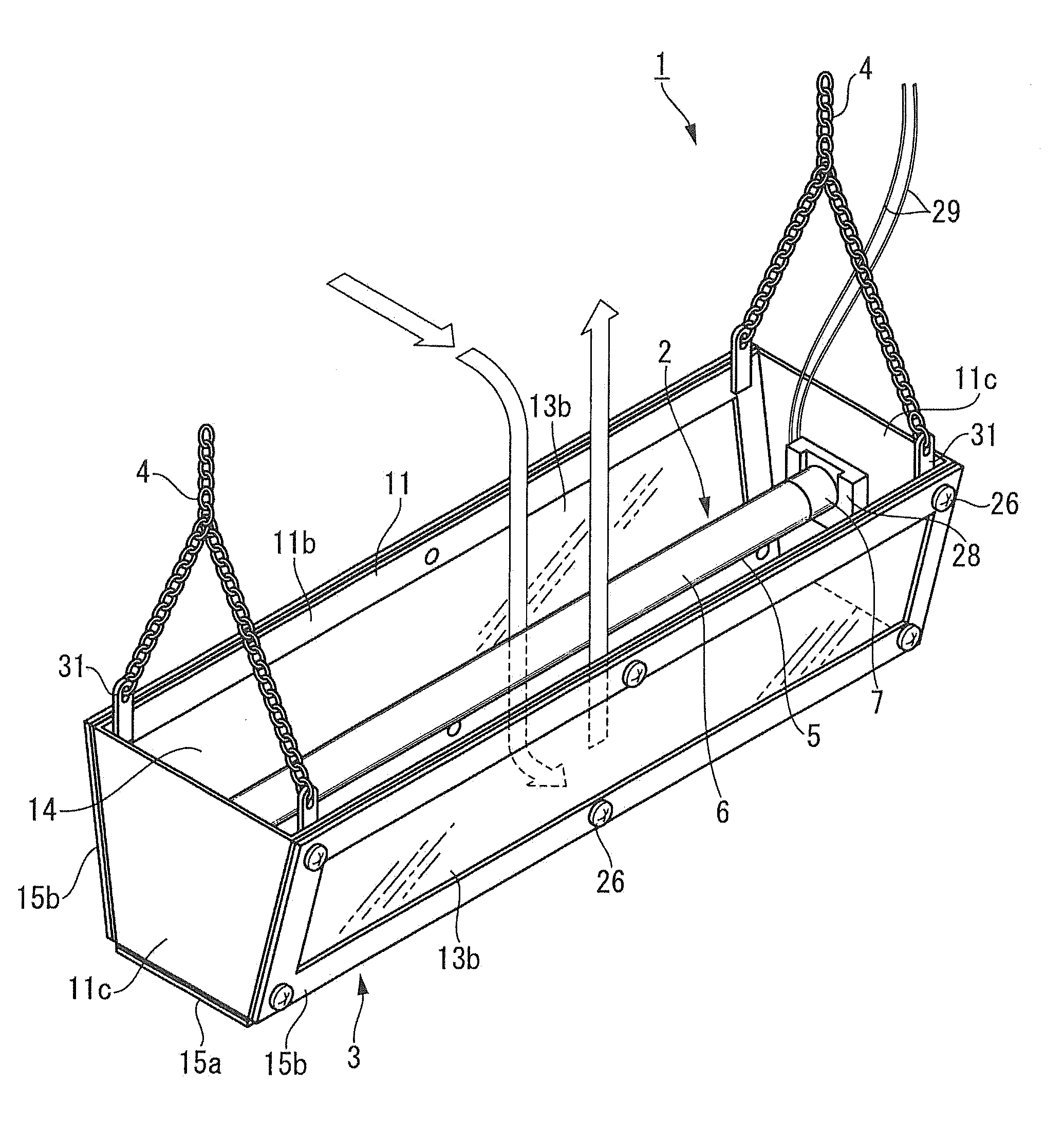
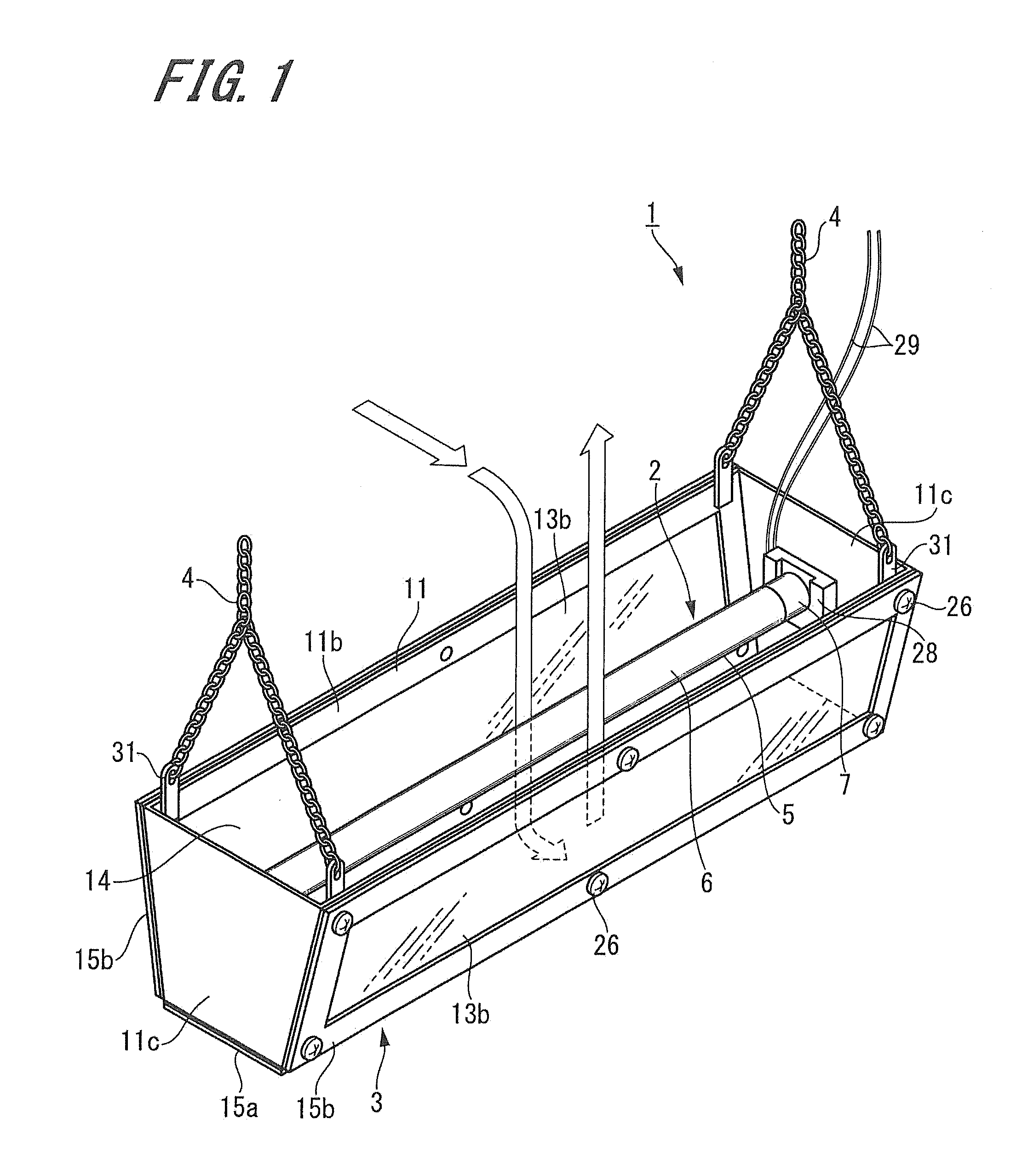
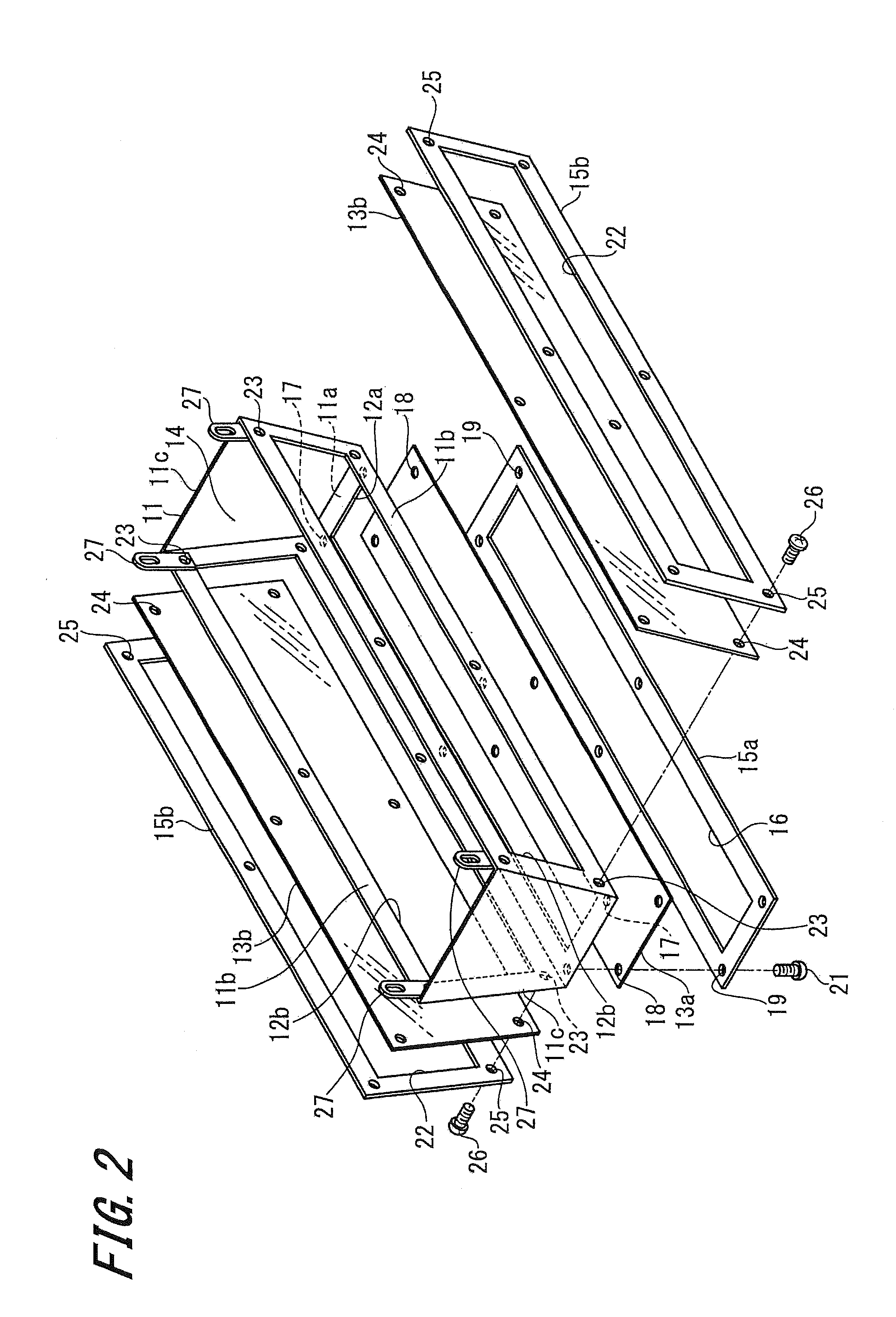
[0072]Embodiments of a lighting and air cleaning device according to the present invention will be described below with reference to the accompanying drawings. FIGS. 1 to 6 show the first embodiment of the lighting and air cleaning device according to the present invention. A lighting and air cleaning device 1 described as the first embodiment includes an electromagnetic wave generation source 2 that emits electromagnetic waves including ultraviolet rays, an ultraviolet-shielding resin member 3 that houses the electromagnetic wave generation source 2, and a hanging unit 4.

[0073]The electromagnetic wave generation source 2 emits electromagnetic waves including an electromagnetic wave (ultraviolet rays) in a wavelength range of 180 (nanometers) to 379 nm and an electromagnetic wave (visible light rays) in a wavelength range of 380 to 780 nm. Examples of this electromagnetic wave generation source 2 can include an ultraviolet lamp, and an ultraviolet generation LED, a semiconductor lig...

second embodiment

[0106]FIG. 7 is a diagram showing the second embodiment of the lighting and air cleaning device according to the present invention. A lighting and air cleaning device 40 shown in this embodiment includes the ultraviolet lamp 5 that is an electromagnetic wave generation source, and a cover and casing 41 that indicates a second specific example of the ultraviolet-shielding resin member. The cover and casing 41 is formed of a horizontally long enclosure having an opening portion 42 in an upper surface. The cover and casing 41 has a horizontally long rear surface portion 41a that serves as a fixation base, a horizontally long lower surface portion 41b that continuously protrudes forward on the lower portion of the rear surface portion 41a, a front surface portion 41c that continuously rises upward on the front portion of the lower surface portion 41b, and a pair of side surface portions 41d, 41d that rises continuously on both sides in the longitudinal direction.

[0107]The entire cover a...

third embodiment

[0113]FIG. 8 is a diagram showing the third embodiment of the lighting and air cleaning device according to the present invention. A lighting and air cleaning device 50 described in this embodiment includes the ultraviolet lamp 5 that is an electromagnetic wave generation source, and a cover enclosure 51 showing a third specific example of the ultraviolet-shielding resin member. The lighting and air cleaning device 50 according to the third embodiment differs from the lighting and air cleaning device 40 according to the second embodiment in that a pair of sockets 28, 28 is fixed to predetermined positions of a building or the like, and that the cover enclosure 51 can be hung from the ultraviolet lamp 5 held between the pair of sockets 28, 28. Hence, the cover enclosure 51 will be described here, and overlapped description will not be repeated, with the same parts as in the first and second embodiments identified with like symbols.

[0114]The cover enclosure 51 is formed of a horizonta...


PUM

PropertyMeasurementUnit
wavelength rangeaaaaaaaaaa
wavelengthaaaaaaaaaa

Abstract

An ultraviolet lamp, and an ultraviolet-shielding member that covers at least a part of an ultraviolet emission portion are provided. The ultraviolet-shielding member includes an ultraviolet non-transmissive and visible light transmissive portion that blocks or absorbs ultraviolet rays. Further, an air passage in which air around the ultraviolet emission portion is provided between the ultraviolet lamp and the ultraviolet-shielding member.

Description

TECHNICAL FIELD[0001]The present invention relates to a lighting and air cleaning device that emits an electromagnetic wave from an electromagnetic wave generation source to sterilize bacteria, viruses, and the like floating in the air by utilizing ultraviolet rays in a wavelength region of 180 to 379 nm (nanometers) within the electromagnetic wave (mainly, sterilization rays having a wavelength of 253.7 mm), blocks or absorb the ultraviolet rays for a human, or excites a light emitting substance, and irradiates visible light rays in a wavelength region of 380 to 780 nm, which are present within the electromagnetic wave or which have been generated by exciting the light-emitting material with the ultraviolet rays, to utilize the visible light rays as part of illumination light.BACKGROUND ART[0002]In general, as lightings in homes, offices, and the like, fluorescent lamps (fluorescent tubes) are used, and sterilization lamps (ultraviolet sterilization tubes) are used, for example, fo...

Claims


Application Information

Patent Timeline
Patent Type & Authority Applications(United States)
IPC IPC(8): A61L9/20F24F8/22
CPCA61L9/205F24F2221/14F21K9/17F21S8/037F21S9/037F21V17/06F21V33/0088F21Y2101/02F21Y2103/00F21Y2103/003F21Y2103/025F21Y2105/001F24F3/16F24F2003/1667F24F2221/02A61L2209/12F21Y2105/10F21K9/27F21Y2103/10F21Y2115/10F21Y2103/37F21Y2107/90F24F8/22
Inventor KOJI, MASASHIKOJI, YUYA
Owner HOSHIN KAGAKU SANGYOSHO
Why Eureka
Try Eureka