Attitude control system for small satellites

a satellite and attitude control technology, applied in the field of satellites, can solve the problems of enormous amount of money and effort, failure of traditional satellites, and very little room for innovation, and achieve the effects of avoiding the maintenance of outdated techniques and procedures, and avoiding the development of redundant systems

Inactive Publication Date: 2012-08-09
UNIV OF FLORIDA RES FOUNDATION INC
View PDF10 Cites 70 Cited by
  • Summary
  • Abstract
  • Description
  • Claims
  • Application Information

AI Technical Summary

Benefits of technology

[0030]According to an alternative aspect, a single-gimbaled control moment gyroscope (SGCMG) is provided and includes a flywheel assembly and a gimbal assembly. The flywheel assembly includes a flywheel housing, at least one flywheel rotationally disposed within the flywheel housing, and a flywheel motor configured to drive the flywheel via a drive shaft of the flywheel, wherein the drive shaft of the flywheel has a rotational axis oriented substantially perpendicular to a longitudinal axis extending through the SGCMG. The gimbal assembly includes an L-shaped bracket comprising a first end surface and a second end surface and a gimbal motor having a rotational axis oriented substantially co-axial to the longitudinal axis of the SGCMG, wherein the gimbal motor is coupled to the second end surface and is configured for rotating the flywheel assembly about the longitudinal axis of the SGCMG and between the first end surface and the gimbal motor.
[0031]An additional embodiment is directed to a single-gimbaled control moment gyroscope (SGCMG) also including a flywheel assembly and a gimbal assembly. The flywheel assembly includes a flywheel housing, at least one flywheel rotationally disposed within the flywheel housing, a flywheel motor configured to drive the flywheel via a drive shaft of the flywheel, and at least one flywheel motor driver board coupled to the flywheel housing, wherein the drive shaft of the flywheel has a rotational axis oriented substantially perpendicular to a longitudinal axis extending through the SGCMG. The gimbal assembly includes a bracket comprising a first end surface and a second end surface and a gimbal motor having a rotational axis oriented substantially co-axial to the longitudinal axis of the SGCMG, wherein the gimbal motor is coupled to the second end surface and configured for rotating the flywheel assembly about the longitudinal axis of the SGCMG and between the first end surface and the gimbal motor.
[0032]A further embodiment of the present invention is directed to a method for providing three-axis attitude control of a pico- or a nano-satellite. The method includes providing an attitude control system (ACS) comprising a plurality of single-gimbaled control moment gyroscopes (SGCMG) arranged in a pyramidal configuration, wherein the ACS occupies a volume of less than about 100 mm×100 mm×50 mm of the satellite and has a mass less than about 500 grams. The method also includes controlling the SGCMGs to produce a net torque on the satellite to adjust the attitude thereof.

Problems solved by technology

Failure of traditional satellites is extremely costly hence they tend to utilize space-proven, often outdated technologies, leaving very little room for innovation.
An enormous amount of money and effort is expended into the development of redundant systems and the maintenance of outdated techniques and procedures.
Thus historically, the development of traditional satellites has been limited to countries with large military and / or commercial budgets.
To date, these satellite classes typically use coarse three axis attitude control, or passive control that stabilizes the satellite but fails to provide pointing accuracy.
While these systems have provided some form of attitude control for their experimental mission, the real utility of pico- and nano-satellites cannot be fully realized with these systems.
Both of these systems have limited operational life since the momentum transfer is accomplished through expelled particles which must be stored onboard the spacecraft and once expelled are non-reusable.
These systems require propellant storage, plumbing, and valves for operations which makes them impractical for pico- / nano-satellite applications.
In their current state of development, ion thrusters are impractical for three-axis attitude control due to volume and mass constraints.
Furthermore, they may be incapable of performing rapid slew maneuvers due to their low thrust output.
Since the external torque is a resultant of a vector cross product between the fields, full three axis control is not always possible.
However, they suffer from (i) spatial dependence (i.e., require knowledge of the local magnetic field), (ii) relatively low accuracy, and (iii) singular directions potential attitudes for which magnetic coils become ineffective).
All three systems are susceptible to momentum saturation (e.g., from external disturbances) and require some capabilities for momentum dumping.
These devices are relatively simple in design but require substantial power (i.e., shaft power) due to the direct nature of the application of torque(i.e., the output to input torque ratio is unity) and typically have lower slew rates than CMGs.
One of the drawbacks of this type is the phenomenon of gimbal lock which occurs when the flywheel and gimbal axes align.
In this situation the CMG cannot produce any torque.
The mechanical construction of the DGCMG is more complex.

Method used


Image

  • Attitude control system for small satellites
  • Attitude control system for small satellites
  • Attitude control system for small satellites

Examples


first embodiment

[0125]Flywheel Assembly

[0126]The SGCMG 10 generally includes a flywheel assembly 12, a gimbal assembly 14, and a slip ring assembly 16, as shown in FIGS. 12-14. One particular purpose of the flywheel assembly 12 is to accommodate components required to spin a rotor at high speeds (e.g., 5000 rpm). The flywheel assembly 12 generally includes:[0127]Flywheel housing (36)[0128]Motor (rotor+stator) (32)[0129]Bearings (34)[0130]Snap rings (35)[0131]Flywheel (shaft+endpiece) (30)

[0132]One function of the flywheel assembly 12 is to accommodate a spinning flywheel 30 and its motor 32 that provide the required angular momentum to the SGCMG. The flywheel assembly 12 also provides an interface to the gimbal assembly 14. An exploded view of the flywheel assembly is shown in FIG. 15, which illustrates the flywheel 30 with the motor rotor (magnet) 37 is mountable on a pair of bearings 34 and capable of being disposed within a flywheel housing 36. The flywheel 30 is driven by a brushless DC motor w...

second embodiment

[0160]A second embodiment of a SGCMG 100 is shown in FIGS. 19-20. Generally, the SGCMG 100 includes:

[0161]a) Flywheel housing (136)

[0162]b) Flywheels (130)

[0163]c) Flywheel motor (132)

[0164]d) Flywheel bearings (134)

[0165]e) Flexible couplings (135)

[0166]f) Flywheel motor control boards (137)

[0167]g) L-bracket (150)

[0168]h) Gimbal motor mount plate (152)

[0169]i) Gimbal bearings (156)

[0170]j) Gimbal motor with integrated encoder (154)

[0171]k) Slip ring assembly (116)

The first six components form the flywheel assembly 112 while the remaining components form the gimbal assembly 114.

Flywheel Assembly

[0172]An exploded view of the flywheel assembly 112 is shown in FIG. 21. The construction of the flywheel housing 136 is similar to the flywheel housing 36 described above but with some modifications to accommodate the new motor 132 and flywheels 130. The SGCMG 100 is smaller in size, accommodates two flywheels 130 and has a central plate for the motor mount. The flywheel motor 132 is face m...

third embodiment

[0193]A third embodiment of a SGCMG 200 is shown in FIG. 35, which is a hybrid of the SGCMGs 10, 100 discussed above. The SGCMG 200 was considered to produce more torque for using them in larger satellites (e.g., nano-satellites) [12]. The mass and volume constraints of 500 g and ½ U were still considered applicable. But the power constraint of 3 W was relaxed assuming more power availability in larger satellites. A frameless motor 232, such as a Kollmorgen motor, was again considered for the flywheel assembly 212, while a brushed DC gear motor 254, such as the Micromo 2619 series DC gear motor, was used for the gimbal assembly 214.

[0194]The following are the specifications of the hybrid design:

[0195]1. Mass: <500 g

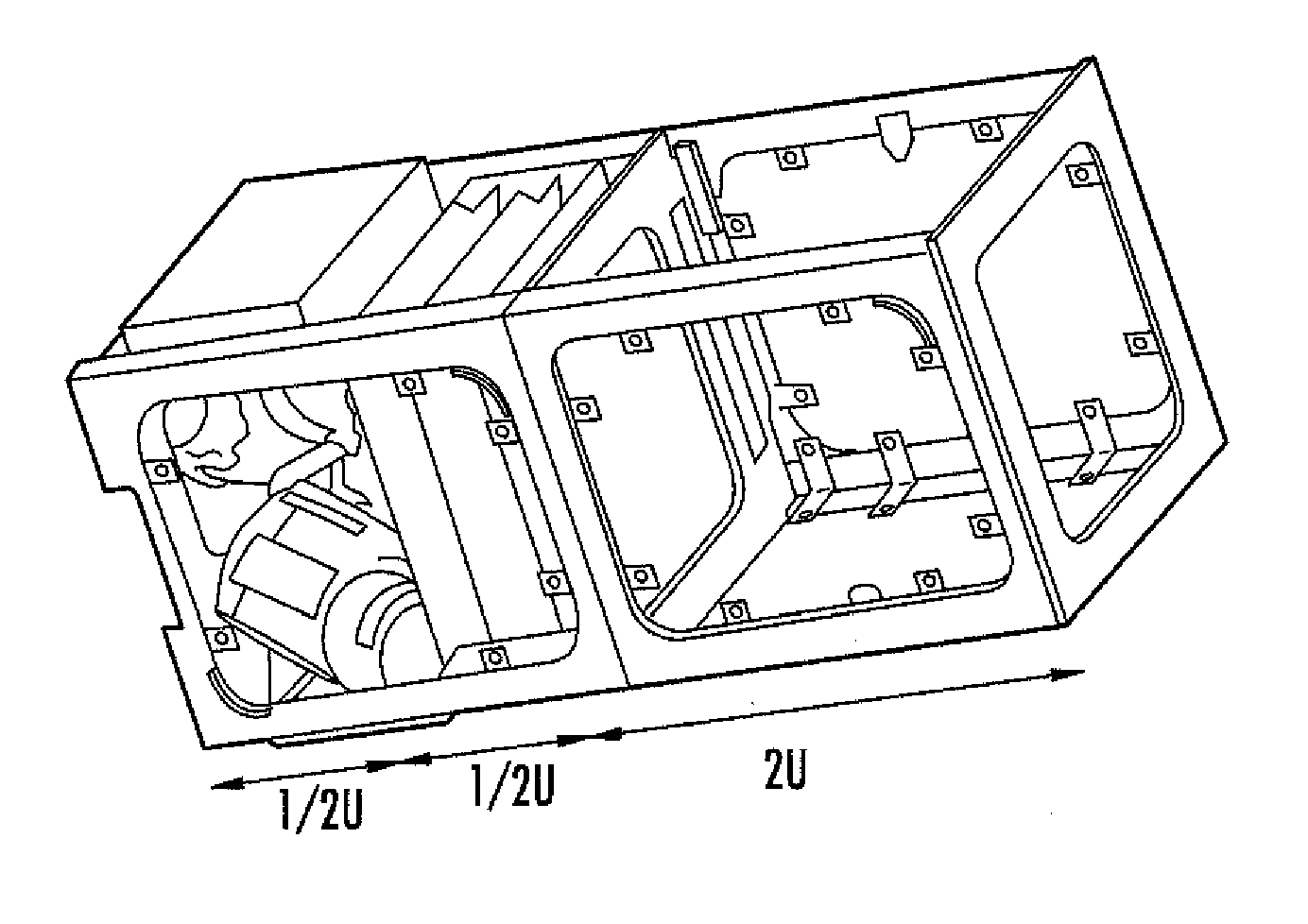
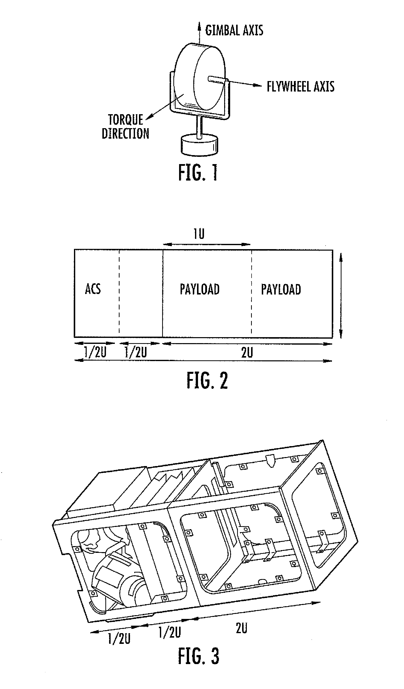
[0196]2. Volume: ½ U (100×100×50 mm3)

[0197]3. Power: 6 W

[0198]4. Flywheel speed: 10000 rpm

[0199]5. Maximum gimbal speed: 1 rad / s

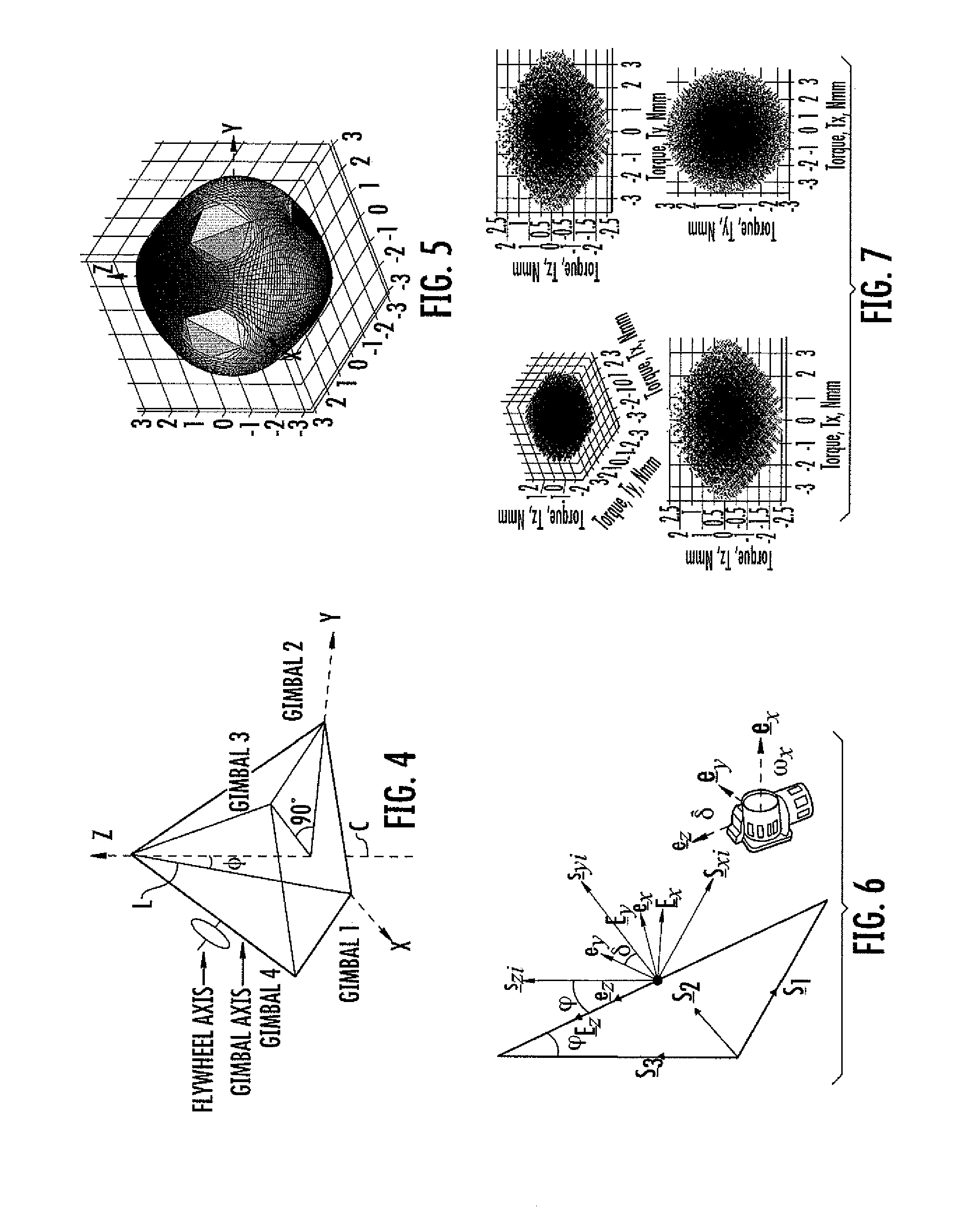
[0200]6. Torque: 3 Nmm

[0201]The torque produced by SGCMG 200 is sufficient for the ACS of a nano satellite whose mass is less than 12 Kg and occ...


PUM


Abstract

Various embodiments of the present invention include an attitude control system for use with small satellites. According to various embodiments, the system allows rapid retargeting (e.g., high slew rates) and full three-axis attitude control of small satellites using a compact actuation system. In certain embodiments, the compact actuation system includes a plurality of single-gimbaled control moment gyroscopes (SGCMG) arranged in a pyramidal configuration that are disposed within a small satellite.

Description

FIELD OF THE INVENTION[0001]Embodiments of the present invention relate to satellites and, more particularly, to systems and methods for attitude control of pico- and nano-satellites.BACKGROUND[0002]During the past decade there has been growing interest within the space industry towards the development of small satellites. Small satellites are typically categorized as picosats (1 kg or less), nanosats (1-10 kg), microsats (10-100 kg) or minisats (100-500 kg) and range in size from softballs to refrigerators. The interest in these satellites is driven by the current constraints of traditional satellites and launch systems. As a result, there has been a significant effort to push satellite technology to smaller sizes and mass, which would enable small satellites to accomplish missions to complement the larger satellites. Examples of such missions include imaging, remote sensing, surveillance, disaster management, and blue force tracking. These missions are achieved by payloads which d...

Claims


Application Information

Patent Timeline
Patent Type & Authority Applications(United States)
IPC IPC(8): B64G1/28G05D1/08G01C19/08B64G1/10
CPCB64G1/286Y10T74/1282B64G1/428
Inventor NAGABHUSHAN, VIVEKFITZ-COY, NORMAN G.LEVE, FREDERICK AARON
Owner UNIV OF FLORIDA RES FOUNDATION INC
Why Eureka
Try Eureka