
Portable Detection Apparatus

Inactive Publication Date: 2012-08-09
CLEAR PATH TECH
View PDF9 Cites 25 Cited by
  • Summary
  • Abstract
  • Description
  • Claims
  • Application Information

AI Technical Summary

Benefits of technology

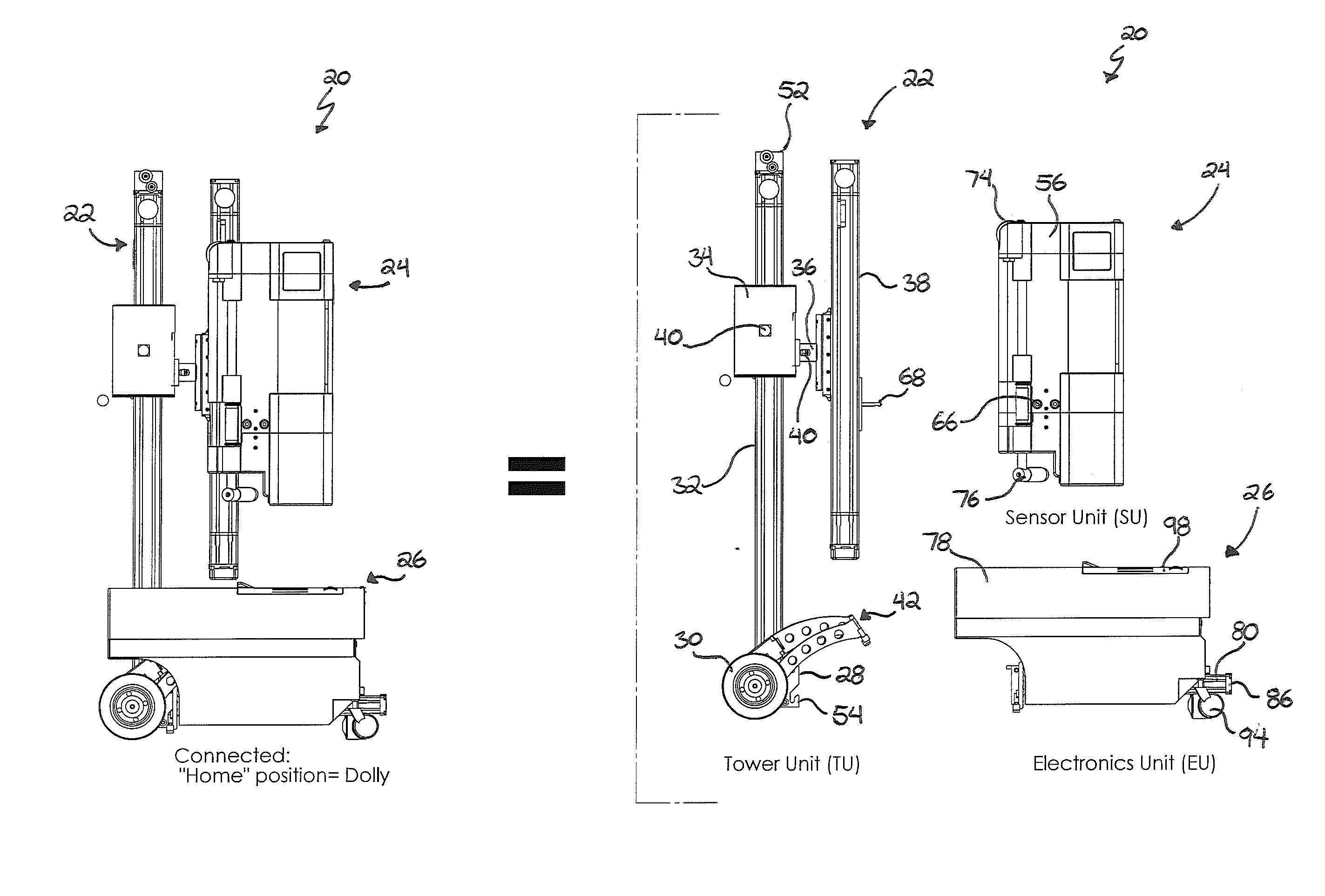
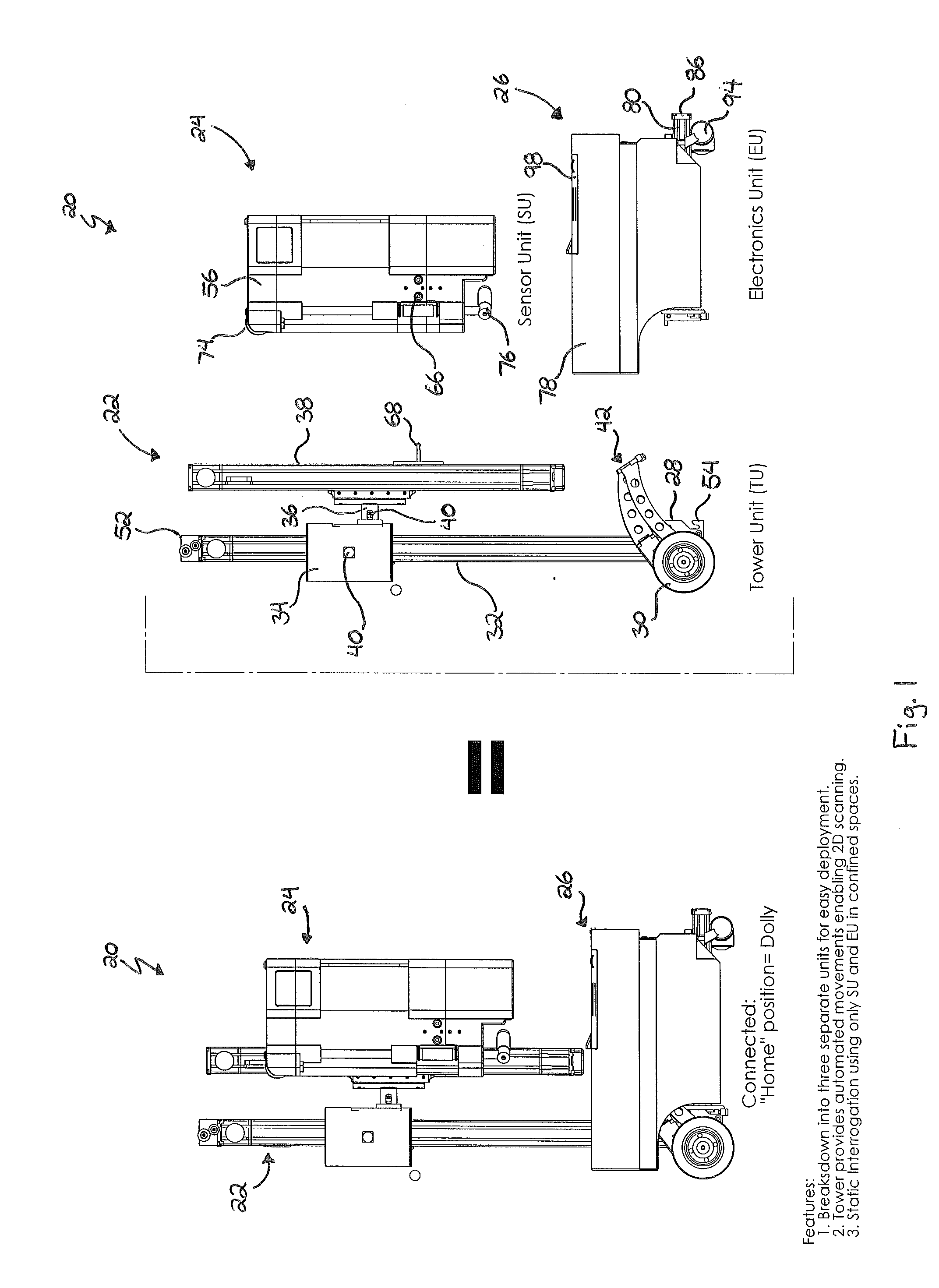
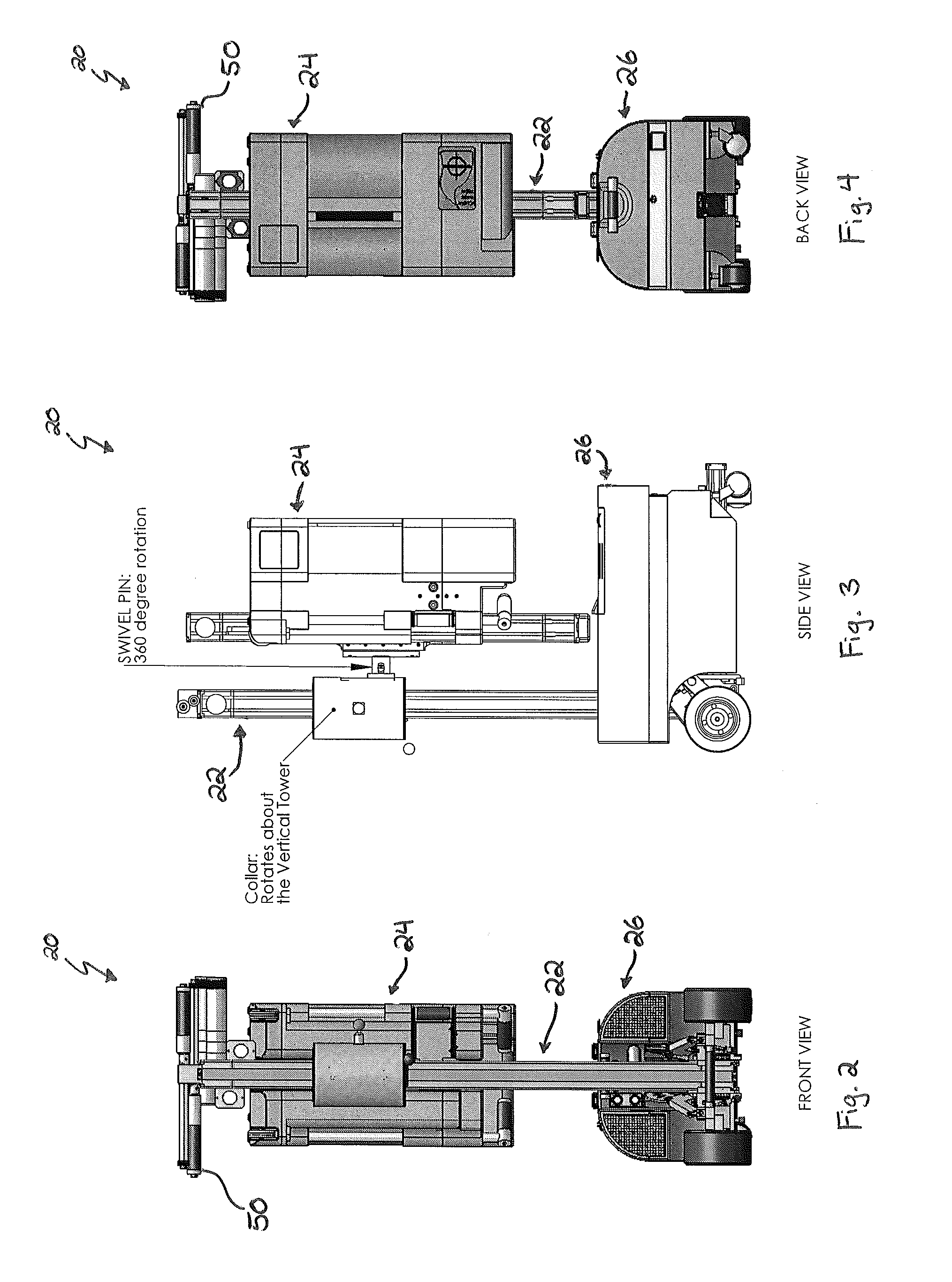
[0023]The apparatus comprises, in an exemplary embodiment, a tower unit, a sensor unit and an electronics unit, each configured to be removably engagable with one another for relatively quick disassembly during transport and storage and reassembly during use. Additionally, each of the units are sized and configured for being able to operate in relatively confined spaces. The tower unit comprises a tower base having a relatively vertically oriented tower column, with a tower collar both slidably and rotatably engaged with the tower column. Thus, the tower collar is able to traverse the length of, as well as horizontally rotate 360 degrees around, the tower column. An arm mount is pivotally engaged with the tower collar and provides a slidably mounted extender arm. This configuration allows the extender arm to vertically rotate 360 degrees relative to the tower collar. Additionally, the extender arm provides a sensor mount configured for selectively receiving a sensor receptacle of the sensor unit. The sensor unit also provides a means for scanning the target object. Thus, with the sensor unit so engaged with the tower unit, the sensor unit is able to articulate into a wide range of positions so as to be selectively positionable adjacent the target object, virtually regardless of the target object's location. The electronics unit is selectively engagable with the tower unit as well, and provides a portable computing device configured for remotely operating the sensor unit a safe distance away from the target object.
[0026]Another objective is to provide such an apparatus that has a modular design that not only allows for relatively easy storage and deployment, but also enables scanning to be performed on objects from many different positions, orientations and angles, as well as at various heights, even when those objects are located in relatively confined spaces.

Problems solved by technology

Additionally, the sheer volume of the current levels of international travel and trade further complicates the problems already associated with inspecting cargo at ports of entry and departure.
Public transportation systems, transportation terminals, airports, hotels, shopping centers, and other large public venues in particular are vulnerable to terrorist attacks, which place entire communities and even national security at risk.
Significant economic losses and interruption of vital services can result from even short-term disruptions.
However, while anomaly detectors are useful for flagging “suspicious” items, they cannot determine for sure whether the object or contents in question actually are explosives, illicit substances, or biological agents, or merely some harmless substance.
However, X-rays suffer from the main disadvantage of having a small interaction probability with the low-electron density elements from which organic materials, including most explosives and illicit drugs, are composed.
Therefore, all these substances have undistinguished X-ray absorption or incoherent scattering characteristics.
Also, X-rays in particular are susceptible to false negatives because of the inability to see through relatively dense shielding or masking that is usually employed to hide contraband and threat materials.
Even though some newer X-ray machines incorporate automated image recognition to determine whether an image indicates a suspicious object instead of relying on the operator, they cannot conclusively identify the contents, so the suspect target still must be opened and manually inspected.
This makes detection by anomaly detectors such as X-rays in many cases unreliable and unsafe and prone to an unacceptable rate of false alarms.
Additionally, current neutron activation / gamma spectroscopy technology, such as fast neutron activation analysis, lacks directionality and range.
As a result, large areas require numerous scans that, in turn, require a significant amount of time and computer processing for an object to be fully interrogated.
Neutron activation based scanning thus presents a number of problems.
First, accurately scanning an entire object using currently known fast neutron activation analysis techniques may be too slow for practical use in certain contexts such as screening luggage in airports.
Second, the more time that a fast neutron activation analysis device scans an object, the more neutron radiation is released into the immediate environment, thus creating the potentially harmful situation of increased radiation exposure for nearby persons.
Additionally, from an equipment standpoint, both the neutron generator and high resolution detector are subject to wear with increased exposure to the neutron emissions.
Third, in order to perform multiple scans of a larger object, the typical neutron activation based scanner must be shut down or deactivated for repositioning then restarted or reactivated between successive scans, thus increasing the amount of time to fully interrogate the object as well as the time the user spends near the object or in the immediate area of risk while repositioning.
A further disadvantage of the prior art approaches is that neutron activation analysis scanning devices have been large and generally immobile.
While this may be efficient in the context of airport luggage screening and the like, it is not effective in other contexts where physically handling or moving the suspect object is inherently dangerous, such as when the object is a parcel or bag left unattended or abandoned in a public area, in an overhead compartment of an airplane, or in other spaces having limited access.
Additionally, in situations where the user is not aware of either the destructive range of or their proximity to the discovered explosive, there is a great deal of danger for both the user and the nearby public.
However, the prior art fails to teach such a portable detection apparatus having a modular design that not only allows for relatively easy storage and deployment, but also enables scanning to be performed remotely on objects of varying dimensions from many different positions, orientations and angles, as well as at various heights, even when those objects are located in relatively confined spaces.

Method used


Image

  • Portable Detection Apparatus
  • Portable Detection Apparatus
  • Portable Detection Apparatus

Examples


Embodiment Construction

[0047]The above described drawing figures illustrate aspects of the invention in at least one of its exemplary embodiments, which are further defined in detail in the following description.

[0048]Turning now to FIG. 1, there is shown a side elevational view of an exemplary embodiment of a portable detection apparatus 20. The apparatus 20 comprises, in the exemplary embodiment, a tower unit 22, a sensor unit 24, and an electronics unit 26, each configured to be removably engagable with one another as best shown in FIGS. 1-4. Thus, these three modular units 22, 24 and 26 are capable of being quickly disassembled for transport and storage, and reassembled to perform scans after deployment to a target site. Additionally, each of the units 22, 24 and 26 are sufficiently compact and narrow to allow the apparatus 20 to fit in relatively confined spaces, such as an aisle in a commercial airplane.

[0049]With continued reference to FIGS. 1-4, the tower unit 22 comprises, in the exemplary embodi...


PUM


Abstract

A portable detection apparatus for scanning a target object comprises, in an exemplary embodiment, a tower unit, sensor unit and electronics unit, each configured for removable engagement with one another for relatively quick disassembly during transport and storage and reassembly during use. Additionally, each unit is sized and configured for ease of transport and for being able to operate in relatively confined spaces. The sensor unit is configured for selective engagement with a vertically oriented tower column of the tower unit, and is capable of not only traversing the length of the tower column but also rotating both horizontally and vertically thereabout, allowing the sensor unit to articulate and be selectively positionable adjacent the target object regardless of the target object's location. The electronics unit is selectively engagable with the tower unit and provides a portable computing device configured for remotely operating the sensor unit a safe distance away.

Description

RELATED APPLICATIONS[0001]This application claims priority and is entitled to the filing date of U.S. Provisional Application Ser. No. 61 / 227,199, filed Jul. 21, 2009 and entitled “Portable Detection Apparatus.” The contents of the aforementioned application are incorporated herein by reference.INCORPORATION BY REFERENCE[0002]Applicant hereby incorporates herein by reference any and all U.S. patents and U.S. patent applications cited or referred to in this application.TECHNICAL FIELD[0003]Aspects of this invention relate generally to scanning devices, and more particularly to a portable, multi-planar detection apparatus configured for scanning suspect objects to determine whether they contain explosive or other threat or illicit materials.BACKGROUND ART[0004]Generally speaking, the current trend of increased terrorist activity, including the tragic events of the September 2011 attacks, the London and Madrid transit bombings, the Mumbai urban attacks, and the like, along with the gro...

Claims


Application Information

Patent Timeline
IPC IPC(8): G01N23/02
CPCG01V5/0008G01V5/20G01V2210/72
Inventor CHUANG, TSUEY FENMORRISON, II, DAVID F.SINCLAIR, RICHARD CALVINSLACK, BRYAN LEESPILLMANN, ROGER W.A.STANICH, VLADIMIR
Owner CLEAR PATH TECH
Learn More