Power Or Voltage Oscillation Damping In A Power Transmission System

a power transmission system and power or voltage oscillation technology, applied in the direction of power oscillation reduction/prevention, system intergating technologies, ac network circuit arrangements, etc., can solve the problems of insufficient damped oscillation, loss of synchronism, loss of interconnection, etc., to avoid local and wide-area power or voltage oscillation damping, high observability of oscillation

Inactive Publication Date: 2012-08-09
ABB POWER GRIDS SWITZERLAND AG +1
View PDF3 Cites 21 Cited by
  • Summary
  • Abstract
  • Description
  • Claims
  • Application Information

AI Technical Summary

Benefits of technology

[0014]The invention according to these aspects enables canceling out of oscillations using an adaptively changed phase compensation angle. This can be implemented without prior knowledge of a post-fault operating condition. The invention is furthermore flexible in that any measurement signal that have high observability of the oscillation can be used without any significant modification. T

Problems solved by technology

Insufficiently damped oscillations may occur when the operating point of the power system is changed, for example, due to a new distribution of power flows following a connection or disconnection of generators, loads and/or transmission lines.
In these cases, an increase in the transmitted power of a few MW may make the difference between stable oscillations and unstable oscillations which have the potential to cause a system collapse or result

Method used


Image

  • Power Or Voltage Oscillation Damping In A Power Transmission System
  • Power Or Voltage Oscillation Damping In A Power Transmission System
  • Power Or Voltage Oscillation Damping In A Power Transmission System

Examples


first embodiment

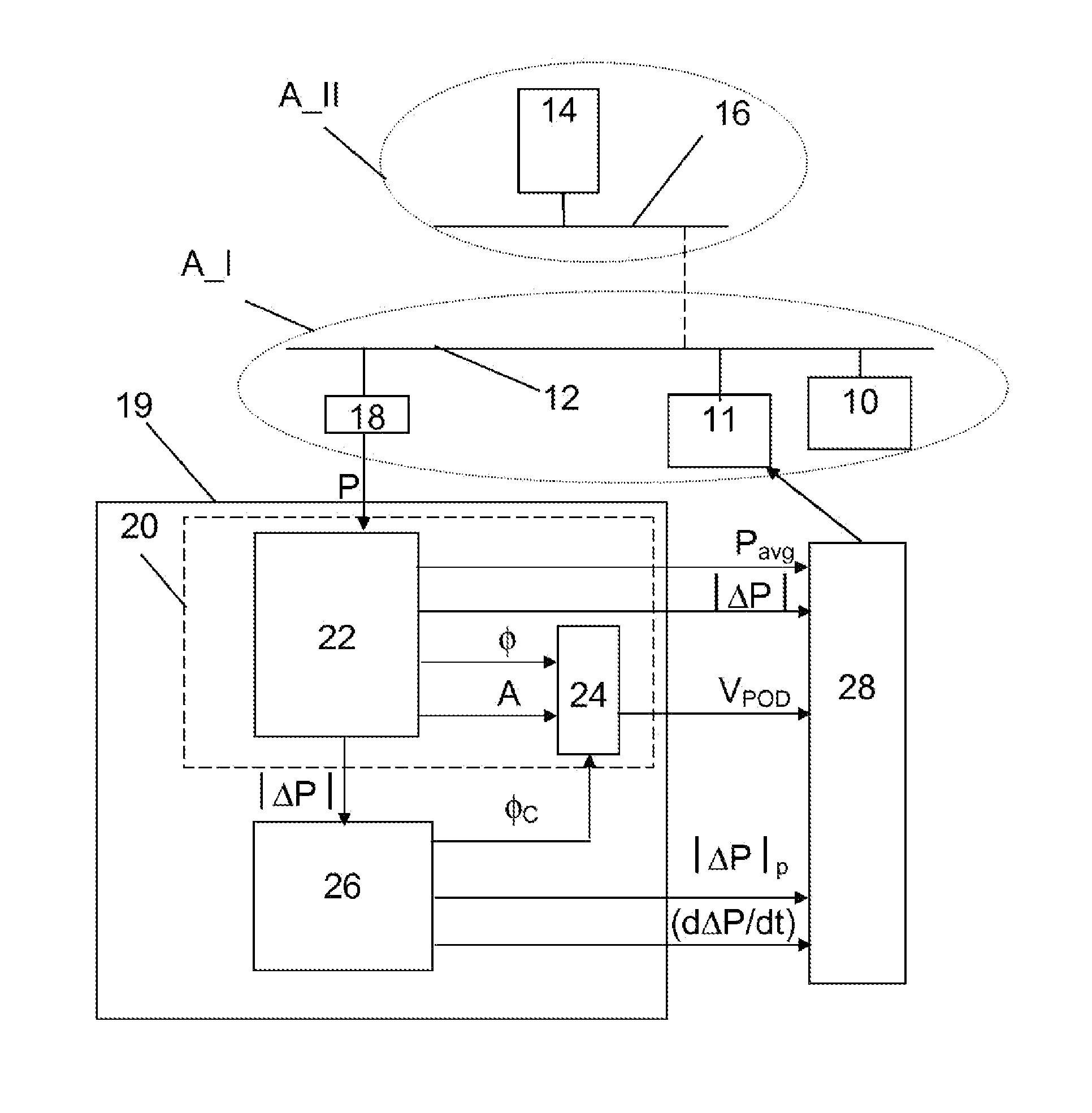
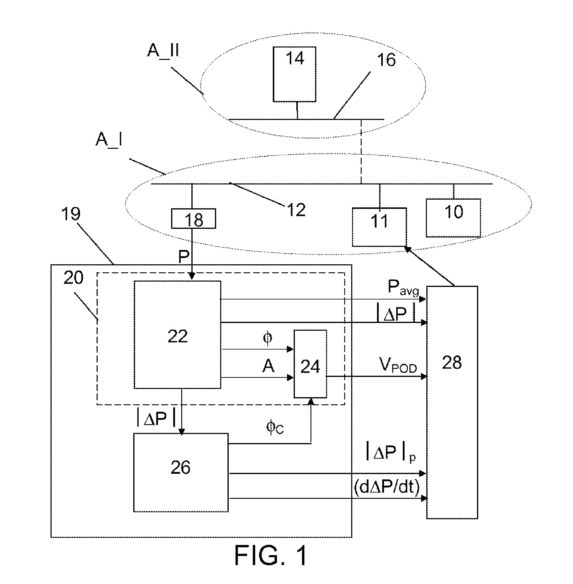
[0032]FIG. 1 schematically shows a simplified power transmissions system in which a device for providing improved control of power or voltage oscillation damping according to the invention is provided. The power transmission system is preferably an AC power transmission system and then operating at a network frequency such as 50 or 60 Hz.

[0033]The power transmission system includes a number of geographical areas, which are here two areas A_I and A_II. These areas are indicated through dotted ellipses and are typically provided on great distances from each other, where one may as an example be provided in the south of Finland and another in the south of Norway. A geographical area is here a coherent area. A coherent area is an area where a group of electrical machines, such as synchronous generators, are moving coherently, i.e. they are oscillating together. Such an area may also be considered as an electrical area, because the machines are close to each other in an electrical sense....

second embodiment

[0068]According to a variation of the second embodiment it is also possible that the system operation reflecting signal is a signal reflecting a property in only one element, a remote element far from the phasor POD device.

[0069]As can be seen in FIG. 7, it is possible that several areas may swing against each other. This swinging can also take place simultaneously. It is therefore possible that a combining unit 91 provides one system operation reflecting signal that is made up of several such swings. A deviating oscillation may thus be multimodal. The system operation reflecting signal is thus a combined signal reflecting a measured power property, like voltage, of more than one system element, here two. It here reflects the power property both in respect of the operating frequency and more than one oscillatory component. Such a combined signal may here be provided through generating a number of difference phasors each being provided as the difference between the phasors of two geo...


PUM


Abstract

A method, device and computer program product for providing improved control of power or voltage oscillation damping in a power transmission system. The device includes a magnitude obtaining element configured to obtain an instantaneous magnitude of a signal representing a deviating oscillation in at least one element of the power transmission system, a slope investigating element configured to determine the rate of change of the signal, and a first processing block including an integrating element configured to integrate the instantaneous magnitudes with an integrating factor that is based on the determined rate of change. The first processing block is further configured to form a phase compensation angle based on the integrated instantaneous magnitude for use in a damping control signal generating unit in order to provide power or voltage oscillation damping of the system.

Description

CROSS-REFERENCE TO RELATED APPLICATIONS[0001]The present application is a continuation of pending International patent application PCT / EP2009 / 060245 filed on Aug. 6, 2009 which designates the United States and the content of which is incorporated herein by reference.FIELD OF THE INVENTION[0002]The invention relates to the field of power or voltage oscillation damping in electric power transmission systems. The invention more particularly concerns a method, device and computer program product for providing improved control of power or voltage oscillation damping in a power transmission system.BACKGROUND OF THE INVENTION[0003]Inter-area modes of oscillation are typically characterised by a group of machines in one geographical area of a power transmission system swinging against a group of machines in another geographical area of the system. Inter-area modes of oscillation is for instance described in CN 101202451, U.S. Pat. No. 6,252,753 and EP 1852952.[0004]These oscillations are in...

Claims


Application Information

Patent Timeline
IPC IPC(8): H02J3/24
CPCH02J3/24Y04S10/265Y02E60/728Y02E60/00Y04S10/00Y04S10/22Y02E40/70H02J3/242
Inventor BERGGREN, BERTILMAJUMDER, RAJATRAY, SWAKSHARCHAUDHURI, BALARKOCHAUDHURI, NILANJAN RAY
Owner ABB POWER GRIDS SWITZERLAND AG
Why Eureka
Try Eureka